Stud Factors
John Siegenthaler, PE
Part of any credible procedure for estimating building heat loss involves determining the total R-values for building panels (e.g., walls, ceilings or floors) that separate heated from unheated space. This is usually done by looking up the R-values of the materials that make up the exposed panel.
Once the R-value of each material is found, a simplistic approach is to add all the R-values together to get the total R-value of the surface. Included in this total are the R-values of all the materials, as well as the inside and outside air films. The latter are the thermal resistances of two thin layers of air that cling to the inside and outside of the panel.
Although it's easy to just add R-values together, the result tends to overrate the actual R-value of a wall that contains framing members such as studs and joists. This happens because the thermal resistance of the wood studs or joists is often significantly lower than that of the insulation in the adjacent cavities. The wooden framing members form a path through which heat can move faster than through the surrounding insulation.
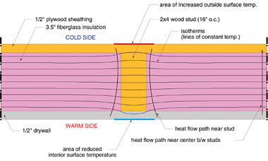
Figure 1 shows a computer simulation of the effects of the wood stud in an otherwise sandwiched construction of drywall, fiberglass insulation and exterior plywood. Notice how the isotherms (lines of constant temperature) are “warped” near the stud.
This indicates that heat is not traveling straight out through the wall as it does at the halfway point between studs (e.g., near the edges of the construction shown). Instead, the better-conducting stud forms a “bridge” across which heat is finding a partial detour around the higher- resistant materials.
The increased rate of heat transfer through the studs causes the inside surface temperature of the panel to be lower at the stud or joist locations. This is indicated by the inward curvature of the isotherm near the inside wall surface.

This condition is worsened by steel studs or purlins that span through the thickness of the wall. A classic example is a truck garage with metal framing and interior cladding. In a cold climate, it doesn't take long before streaks from condensing diesel exhaust appear on light colored interior metal surfaces.
On a smaller level, some of you have also seen how nail heads or screw heads can discolor the inside surface of an exposed wall or ceiling that's poorly insulated. Like a stud, the metal nail or screw forms a high conductance path, and thus lowers the temperature of the inside surface, in some cases enough to cause condensation of water vapor in the surrounding air.
Notice how the isotherm near the outside of the stud is also curved outward. This indicates a higher outside surface temperature near the stud. This higher temperature is what makes framing areas “glow” in an infrared thermogram of the wall as shown in Figure 2.
Making Adjustments
It's possible to account for the higher rates of heat transfer through a wood-framed surface such as a wall, ceiling or floor. The concept is to calculate an “effective total R-value” for the surface based on the type of insulation, the depth of the framing, and the spacing of the framing. This effective total R-value is then used in the heat transfer calculations.Formula 1 can be used to find the effective total R-value of the panel:
-
Where:
- ft2
- hr./Btu)
pf = percentage of panel occupied by framing (decimal percent)
Rf= R-value of a panel section through the framing (degrees F - ft2
- hr./Btu)
Ri = R-value of a panel section through the insulation cavities (degrees F - ft2
- hr./Btu)
Reffective = effective total R-value of the panel (degrees F

Typical wood-framed residential and light commercial construction have from 10 percent to 20 percent of the wall area as solid framing across the insulation cavity. The lower end of this range is appropriate for 24 inches on-center framing, with insulated headers over windows and doors. The upper end is typical for 16 inches on-center framing with solid headers, and complex wall shapes that often necessitate extra studs.
Here's an example of how to use Formula 1 using the wall construction shown in Figure 3.
The R-values of the individual building materials (including the inside and outside air films) have been tallied both between the framing and at the framing. These values are then substituted into Formula 1, assuming 15 percent of the wall is solid framing:

Some energy codes/standards now require that the effective R-value of the various building panels to be used in any calculations to demonstrate compliance with the code/standard. Some heat load estimating software also adjusts for the presence of wood framing in typical residential and light commercial construction.
To minimize the effect of greater heat conduction through framing, the panel should include at least one continuous layer of insulating material across the entire surface area. A good example would be rigid foam sheathing over the outside of the framing. Another would be the use of stressed skin panels that minimize or even eliminate traditional through-the-wall framing.
Consider the well-insulated ceiling assembly shown in Figure 4. The blown fiberglass insulation essentially “buries” the bottom chord of the roof truss framing.
Here is the tally of the R-values both at and between the framing:
Applying Formula 1 to this situation yields an effective total R-value very close to that obtained by simply adding the R-values of the materials and air films:
Thus, the reduction in R-value is more significant when framing members pass most of the way through the wall or otherwise displace materials that add significantly to the total wall R-value.
Use this information to accurately estimate the heat loss through walls, ceilings and floors. If you use software for heating load calculations, find out if it compensates for the presence of framing in building panels. Remember, the more accurate your load calculations, the more precisely you can design your hydronic heating systems. Always aim for the bull's-eye.
Looking for a reprint of this article?
From high-res PDFs to custom plaques, order your copy today!