Variations On Residential Solar Water Heating
Learn about closed loop/antifreeze-based systems.

Current interest in solar thermal technology is - to say the least - hot! Every month, more vendors enter the North American market with new hardware. Training programs for implementing this hardware are usually filled to capacity. At our office, inquiries about use of solar thermal technology come in almost every day. If you plan to work in the HVAC field over the next decade, chances are you will deal with solar thermal technology in some capacity.
Of all the potential loads that can be served by a solar thermal system, domestic water heating ranks No. 1. The primary reason is that domestic water heating is a year-round load. It takes advantage of the high solar availability in warmer months to boost the total amount of energy harvested per square foot of collector per year. This allows solar water heating systems to provide better returns on investment relative to solar systems designed for space heating.
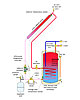
In 1909, an engineer named William Bailey put forth a new design concept that separated the solar collector and storage tank and, thus, greatly reduced nighttime heat loss. It was appropriately named the Day and Night Solar Water Heater. It operated on the principle of thermosyphoning. Hot water in the collector rose upward through sloped piping leading to a storage tank mounted at a higher elevation. At the same time, cooler water at the bottom of the tank flowed back to the collector. The concept is shown in Figure 1.
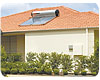
This concept continued to be refined through the first half of the 20th century, and the market flourished in sunny locations such as Florida and Southern California. This concept continues to be used, but with much improved insulation and manufacturing methods. It is now commonly deployed with the storage tank mounted on the outside of the roof, directly above the collectors, as seen in Figure 2.
Many of these passive systems do not have automatic freeze protection. When freezing is imminent, the collector and perhaps even the storage tank must be manually drained. This is unrealistic for cold climates where the potential for freezing exists several months of the year. Hence the market for these systems is warm climates like the extreme southern United States and lower latitudes where freezing rarely, if ever, occurs. There are hundreds of thousands of these systems used in warm climates aound the world.
Here, as in most active solar thermal systems, the collector circulator is operated by a differential temperature controller. It measures the temperature at the outlet of the collector array and in the lower portion of the storage tank. When the temperature of the collector is a set amount above that of the tank (typically 5 to 10 degrees), the circulator is turned on. When this differential drops to a set lower value (typically 1 to 3 degrees), the circulator is turned off. The goal is to “harvest” any solar energy whenever the collector is slightly warmer than the water in the storage tank.
When the circulator is on, an antifreeze solution (typically a 40 to 50 percent solution of nontoxic propylene glycol) flows through the collectors’ circuit. The heat it absorbs from the collectors is carried to and dissipated from the tank’s internal heat exchanger. In some systems, the speed of the collector circulator is varied depending on the temperature differential between the collectors and the tank. The greater the difference, the faster the circulator runs. This helps reduce on/off cycling during low or highly variable solar intensities.
A check valve in the collector circuit prevents “reverse thermosyphoning,” which could otherwise occur when the tank is warmer than the collectors. This phenomenon allowed much of the daily heat gained by early generation passive solar water heating systems to be dissipated at night.
Notice that the check valve is positioned below the point where the expansion tank connects to the circuit. This important detail allows fluid to come down the supply pipe and into the expansion tank should boiling ever occur in the collectors. Although not a common occurrence, it can happen under “stagnation” conditions, such as during a power outage on a hot/sunny summer afternoon.
Positioning the check valve between the purging valves also allows for simple filling and purging. The premixed antifreeze solution is pumped into the downstream valve and proceeds up through the collector array. The developed pressure backseats the check valve. As the fluid moves through the circuit, it pushes air ahead of it. Eventually the air exits through the outlet purging valve.
Any residual air is eventually captured and expelled by the air separator.
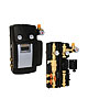 The collector circuit also contains an expansion
tank, pressure relief valve and pressure gauge. All these components can be
individually purchased and assembled, but the trend in the industry is to sell
them as a preassembled “solar circulation station” such as shown in Figure 4.
This pre-engineered assembly contains all the necessary hardware for an antifreeze-based
solar water heating system, and significantly reduces installation
time.
The collector circuit also contains an expansion
tank, pressure relief valve and pressure gauge. All these components can be
individually purchased and assembled, but the trend in the industry is to sell
them as a preassembled “solar circulation station” such as shown in Figure 4.
This pre-engineered assembly contains all the necessary hardware for an antifreeze-based
solar water heating system, and significantly reduces installation
time.
Another significant difference between current systems and their predecessors is the tubing used for the collector circuit. In the old days, soldered copper tubing was the norm. Although it generally worked fine, assembling and soldering copper piping in an attic, or up on a roof, certainly presented its challenges. Today, many of the plug-and-play systems are supplied with flexible stainless-steel tubing. All connections are done with wrenches; no soldering is required. A harness of pre-insulated stainless-steel tubing (supply and return tube, plus a cable for the collector sensor) is simply uncoiled and installed “factory clean.” The lack of solder flux and other contaminants means a lot when it comes to long-term stability of glycol-based antifreeze solutions.
There will be times when the solar energy available is insufficient to supply adequate hot water. Auxiliary heat provides the necessary boost and can be added in several ways. One of the simplest is a single electric-resistance heating element mounted near the top of the solar storage tank. This placement ensures water leaving the tank is adequately heated, while minimizing heat transfer to water in the lower portion of the tank. Keeping the lower portion of the tank as cool as possible improves the performance of the heat exchanger and solar collectors.
 Every solar water heating system must include an
anti-scald-rated tempering valve at the point where it delivers hot water to
the building’s plumbing. There will be times when the temperature in the solar
storage tank is likely to be 180 degrees F or hotter. An example would be after
two or three sequential sunny days, especially if demand for hot water is low.
Water at such temperatures can cause an instant burn at the
fixtures.
Every solar water heating system must include an
anti-scald-rated tempering valve at the point where it delivers hot water to
the building’s plumbing. There will be times when the temperature in the solar
storage tank is likely to be 180 degrees F or hotter. An example would be after
two or three sequential sunny days, especially if demand for hot water is low.
Water at such temperatures can cause an instant burn at the
fixtures.
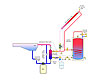
All solar domestic water systems are likely to experience stagnation conditions several times during their life. Collectors rated to the OG-100 standard by the Solar Rating and Certification Corporation are tested to verify they can withstand stagnation. However, extended time at high temperatures degrades glycol-based antifreeze fluids. For this reason, some solar water heating systems include provisions for “dumping” heat to another load, such as a swimming pool (see Figure 5).
In some systems, excess heat is dumped to the outside air are through a “solar convector.” Keep in mind that stagnation can be the result of a power outage. If such outages are common where the system is installed, it’s wise to provide a heat dump method that can operate without utility-supplied power.
Still another variation combines a single solar storage tank with a modulating tankless water heater, as shown in Figure 7.
 This approach avoids the standby heat loss and floor
space required for a second tank. A diverter valve operated by a temperature
controller directs water from the solar storage tank through the tankless water
heater when necessary, or completely bypasses that heater if the water is
already hot enough. All flow must pass through the anti-scald-rated
thermostatic valve prior to heading to the fixtures.
This approach avoids the standby heat loss and floor
space required for a second tank. A diverter valve operated by a temperature
controller directs water from the solar storage tank through the tankless water
heater when necessary, or completely bypasses that heater if the water is
already hot enough. All flow must pass through the anti-scald-rated
thermostatic valve prior to heading to the fixtures.
When this approach is used, be sure that the tankless heater planned for the installation is compatible with preheated water. It must be capable of modulating its heat input, or have a small storage volume to ensure stable operation of the burner or heating element. On/off tankless water heaters are not suitable for this application.
As you can see, there are many variations on solar water heating systems, even within the category of those using antifreeze fluids for freeze protection. In the July issue of the Solar Heating Report, we’ll look at both draindown and drainback solar water heating systems. They rely on distinctly different methods of freeze protection, and offer both strengths and limitations relative to anti-freeze-based systems.
The Solar Rating and CertifiCation Corp.
www.solar-rating.org
the Solar rating and Certification Corp. currently administers a certification, rating and labeling program for solar collectors, and a similar program for complete solar water heating systems.
The National Renewable Energy Laboratory
www.nrel.gov/gis/solar.html
The national renewable energy laboratory’s geographic information System team analyzes wind, solar, biomass, geothermal and other energy resources. The specific Web site we’ve listed offers solar maps.
The Energy Information Administration
www.eia.doe.gov
The energy information administration is a helpful source for official energy statistics for various markets.
The Database of State Incentives for Renewables & Efficiency
www.dsireusa.org
The Database of State Incentives for Renewables and Efficiency is a comprehensive source of information on state, local, utility and federal incentives that promote renewable energy and energy efficiency.
The American Solar Energy Society
The Solar Energy Industry Association
www.ases.org www.seia.org
These are separate nonprofit trade groups dedicated to the solar energy industry in the United States. the ASES publishes Solar Today and will hold the upcoming Solar 2009 Event, May 12-16, In Buffalo, N.Y. The SEIA co-sponsors Solar Power International, slated for Oct. 27-29, 2009, In Anaheim, Calif.
Figure 1.
Current interest in solar thermal technology is - to say the least - hot! Every month, more vendors enter the North American market with new hardware. Training programs for implementing this hardware are usually filled to capacity. At our office, inquiries about use of solar thermal technology come in almost every day. If you plan to work in the HVAC field over the next decade, chances are you will deal with solar thermal technology in some capacity.
Of all the potential loads that can be served by a solar thermal system, domestic water heating ranks No. 1. The primary reason is that domestic water heating is a year-round load. It takes advantage of the high solar availability in warmer months to boost the total amount of energy harvested per square foot of collector per year. This allows solar water heating systems to provide better returns on investment relative to solar systems designed for space heating.
Figure 2. Image courtesy of Solahart.
A Little History
Before there was electricity, there was solar water heating. In the late 1800s, Clarence Kemp of Baltimore patented the Climax solar water heater. His device consisted of multiple cylindrical tanks that were blackened and mounted in a glass-covered box. This was the predecessor of what is now known as a passive “batch heater.” By the turn of the century, several companies had entered the solar water heating market with variants of this design. However, these devices had an “Achilles heal” - they lost much of the heat collected during a sunny day through subsequent nighttime cooling.In 1909, an engineer named William Bailey put forth a new design concept that separated the solar collector and storage tank and, thus, greatly reduced nighttime heat loss. It was appropriately named the Day and Night Solar Water Heater. It operated on the principle of thermosyphoning. Hot water in the collector rose upward through sloped piping leading to a storage tank mounted at a higher elevation. At the same time, cooler water at the bottom of the tank flowed back to the collector. The concept is shown in Figure 1.
This concept continued to be refined through the first half of the 20th century, and the market flourished in sunny locations such as Florida and Southern California. This concept continues to be used, but with much improved insulation and manufacturing methods. It is now commonly deployed with the storage tank mounted on the outside of the roof, directly above the collectors, as seen in Figure 2.
Many of these passive systems do not have automatic freeze protection. When freezing is imminent, the collector and perhaps even the storage tank must be manually drained. This is unrealistic for cold climates where the potential for freezing exists several months of the year. Hence the market for these systems is warm climates like the extreme southern United States and lower latitudes where freezing rarely, if ever, occurs. There are hundreds of thousands of these systems used in warm climates aound the world.
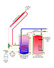
Figure 3.
Active Systems
When circulators enter into the mix, there are many possible system configurations. All of them have a collector array, a storage tank, a circulator controller and a means of freeze protection. Most fall into one of the following categories based on how they provide freeze protection:-
1. Closed loop/antifreeze systems.
2. Draindown systems.
3. Drainback systems.
Here, as in most active solar thermal systems, the collector circulator is operated by a differential temperature controller. It measures the temperature at the outlet of the collector array and in the lower portion of the storage tank. When the temperature of the collector is a set amount above that of the tank (typically 5 to 10 degrees), the circulator is turned on. When this differential drops to a set lower value (typically 1 to 3 degrees), the circulator is turned off. The goal is to “harvest” any solar energy whenever the collector is slightly warmer than the water in the storage tank.
When the circulator is on, an antifreeze solution (typically a 40 to 50 percent solution of nontoxic propylene glycol) flows through the collectors’ circuit. The heat it absorbs from the collectors is carried to and dissipated from the tank’s internal heat exchanger. In some systems, the speed of the collector circulator is varied depending on the temperature differential between the collectors and the tank. The greater the difference, the faster the circulator runs. This helps reduce on/off cycling during low or highly variable solar intensities.
A check valve in the collector circuit prevents “reverse thermosyphoning,” which could otherwise occur when the tank is warmer than the collectors. This phenomenon allowed much of the daily heat gained by early generation passive solar water heating systems to be dissipated at night.
Notice that the check valve is positioned below the point where the expansion tank connects to the circuit. This important detail allows fluid to come down the supply pipe and into the expansion tank should boiling ever occur in the collectors. Although not a common occurrence, it can happen under “stagnation” conditions, such as during a power outage on a hot/sunny summer afternoon.
Positioning the check valve between the purging valves also allows for simple filling and purging. The premixed antifreeze solution is pumped into the downstream valve and proceeds up through the collector array. The developed pressure backseats the check valve. As the fluid moves through the circuit, it pushes air ahead of it. Eventually the air exits through the outlet purging valve.
Any residual air is eventually captured and expelled by the air separator.
Figure 4. Photo courtesy of Caleffi North America.
Another significant difference between current systems and their predecessors is the tubing used for the collector circuit. In the old days, soldered copper tubing was the norm. Although it generally worked fine, assembling and soldering copper piping in an attic, or up on a roof, certainly presented its challenges. Today, many of the plug-and-play systems are supplied with flexible stainless-steel tubing. All connections are done with wrenches; no soldering is required. A harness of pre-insulated stainless-steel tubing (supply and return tube, plus a cable for the collector sensor) is simply uncoiled and installed “factory clean.” The lack of solder flux and other contaminants means a lot when it comes to long-term stability of glycol-based antifreeze solutions.
There will be times when the solar energy available is insufficient to supply adequate hot water. Auxiliary heat provides the necessary boost and can be added in several ways. One of the simplest is a single electric-resistance heating element mounted near the top of the solar storage tank. This placement ensures water leaving the tank is adequately heated, while minimizing heat transfer to water in the lower portion of the tank. Keeping the lower portion of the tank as cool as possible improves the performance of the heat exchanger and solar collectors.
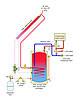
Figure 5.
All solar domestic water systems are likely to experience stagnation conditions several times during their life. Collectors rated to the OG-100 standard by the Solar Rating and Certification Corporation are tested to verify they can withstand stagnation. However, extended time at high temperatures degrades glycol-based antifreeze fluids. For this reason, some solar water heating systems include provisions for “dumping” heat to another load, such as a swimming pool (see Figure 5).
In some systems, excess heat is dumped to the outside air are through a “solar convector.” Keep in mind that stagnation can be the result of a power outage. If such outages are common where the system is installed, it’s wise to provide a heat dump method that can operate without utility-supplied power.
Figure 6.
Two-Tanker
Another common system configuration uses two tanks. A typical example is shown in Figure 6. These systems are common when adding solar collectors to a building that already has a conventional tank-type water heater. The second tank serves at the “auxiliary heater.” No auxiliary heat is added to the solar storage tank. In theory, such systems can gather slightly more solar energy on an annual basis relative to a single-tank system. However, to attain this performance edge, it’s imperative that both tanks are very well-insulated.Still another variation combines a single solar storage tank with a modulating tankless water heater, as shown in Figure 7.
Figure 7.
When this approach is used, be sure that the tankless heater planned for the installation is compatible with preheated water. It must be capable of modulating its heat input, or have a small storage volume to ensure stable operation of the burner or heating element. On/off tankless water heaters are not suitable for this application.
As you can see, there are many variations on solar water heating systems, even within the category of those using antifreeze fluids for freeze protection. In the July issue of the Solar Heating Report, we’ll look at both draindown and drainback solar water heating systems. They rely on distinctly different methods of freeze protection, and offer both strengths and limitations relative to anti-freeze-based systems.
Helpful Websites
Check out these sites for information on solar heating and solar power.The Solar Rating and CertifiCation Corp.
www.solar-rating.org
the Solar rating and Certification Corp. currently administers a certification, rating and labeling program for solar collectors, and a similar program for complete solar water heating systems.
The National Renewable Energy Laboratory
www.nrel.gov/gis/solar.html
The national renewable energy laboratory’s geographic information System team analyzes wind, solar, biomass, geothermal and other energy resources. The specific Web site we’ve listed offers solar maps.
The Energy Information Administration
www.eia.doe.gov
The energy information administration is a helpful source for official energy statistics for various markets.
The Database of State Incentives for Renewables & Efficiency
www.dsireusa.org
The Database of State Incentives for Renewables and Efficiency is a comprehensive source of information on state, local, utility and federal incentives that promote renewable energy and energy efficiency.
The American Solar Energy Society
The Solar Energy Industry Association
www.ases.org www.seia.org
These are separate nonprofit trade groups dedicated to the solar energy industry in the United States. the ASES publishes Solar Today and will hold the upcoming Solar 2009 Event, May 12-16, In Buffalo, N.Y. The SEIA co-sponsors Solar Power International, slated for Oct. 27-29, 2009, In Anaheim, Calif.
Links
Looking for a reprint of this article?
From high-res PDFs to custom plaques, order your copy today!


