Pumping Away - From What?
Not from the boiler, but from the point of no pressure change.
It’s good to periodically review fundamental design concepts. It helps ensure they were fully and correctly understood the first time around, and reinforces that they remain as valid with state-of-the-art hydronics as they were with previous-generation technology.
I doubt if there are many hydronic heating professionals who haven’t heard the term “pumping away.” Still, I occasionally find confusion about what, exactly, we should be “pumping away” from.
Some insist it’s the boiler. About two decades ago, boiler manufacturers started moving circulators on packaged boilers from the inlet to the outlet. Some even provided a wiring harness long enough to allow the circulator to be mounted at either location, at the discretion of the installer.
A cast-iron sectional boiler is, from the standpoint of hydraulics, just a wide spot in the piping circuit. Granted that thermal energy is added at this wide spot, but that has virtually no effect on the hydraulics. This also would be true for other low head loss heat sources such as some fire tube boilers. The boiler is not what we need to pump away from.
To increase the pressure in most of the circuit requires that the differential pressure created by the circulator be added to, rather than subtracted from, the static pressure in the system. To make this happen, the circulator needs to “pump away” from the point of no pressure change (PONPC) in the circuit.
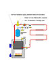
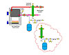
In a simple-series hydronic circuit, the PONPC will always be where the expansion tank connects to the circuit. It follows that the circulator should “pump away” from this point. This is accomplished in the system shown in Figure 1.
This layout is quite popular in North America. The expansion tank threads into the bottom of the air separator. There’s very little pressure drop between the PONPC and the boiler. If the boiler has low head loss characteristics, there also will be very little pressure drop across it as the circulator operates. The pressure relief valve mounted to the boiler experiences very little change in pressure when the circulator turns on. This is good.
 I recommend at least 10 pipe diameters of
straight pipe upstream of the circulator’s inlet flange. This is another “standard
detail” that reduces turbulence into the circulator and keeps things
quiet.
I recommend at least 10 pipe diameters of
straight pipe upstream of the circulator’s inlet flange. This is another “standard
detail” that reduces turbulence into the circulator and keeps things
quiet.
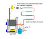
The configuration shown in Figure 2 is less used but just as valid from the standpoint of hydraulics. Although the expansion tank has moved several feet away from the circulator’s inlet, the pressure drop represented by the piping path between the circulator and expansion tank is still very low relative to the pressure drop around the remainder of the distribution circuit. This allows most of the pressure differential created by the circulator to raise the pressure in the distribution circuit.
 This approach also keeps the expansion tank on
the “cool” side of the heat source. Reduced heating of the expansion tank shell
reduces both static pressure increases and extraneous heat loss from the
system. It’s also likely that tanks operating at lower temperatures will have
longer diaphragm life.
This approach also keeps the expansion tank on
the “cool” side of the heat source. Reduced heating of the expansion tank shell
reduces both static pressure increases and extraneous heat loss from the
system. It’s also likely that tanks operating at lower temperatures will have
longer diaphragm life.
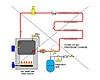
Avoid the system shown in Figure 3. This design allows the pressure differential created by the circulator to add to the pressure in the boiler. Although the boiler is probably more than capable of handling the increased pressure, the pressure relief valve piped to the boiler also feels the pressure increase. Depending on the static pressure in the system, it’s possible the relief valve could start dribbling or open when the circulator turns on.
In systems with a hydraulic separator, the expansion tank can be placed almost anywhere in the vicinity of the hydraulic separator. I typically show it near one of the lower connections (e.g., system return or boiler return). Some hydraulic separators even have a tapping or extension near the bottom to which the expansion tank can connect. Although fine from a hydraulics standpoint, I urge you to install the tank so that sediment that may accumulate at the bottom of the hydraulic separator will not drop down onto the top of the expansion tank’s diaphragm. Use a tee and some elbows to offset the expansion tank as shown in Figure 5.
Pumping away means away from the point of no pressure change rather than away from the boiler. Use it on every installation and enjoy the benefits.
Figure 1.
It’s good to periodically review fundamental design concepts. It helps ensure they were fully and correctly understood the first time around, and reinforces that they remain as valid with state-of-the-art hydronics as they were with previous-generation technology.
I doubt if there are many hydronic heating professionals who haven’t heard the term “pumping away.” Still, I occasionally find confusion about what, exactly, we should be “pumping away” from.
Some insist it’s the boiler. About two decades ago, boiler manufacturers started moving circulators on packaged boilers from the inlet to the outlet. Some even provided a wiring harness long enough to allow the circulator to be mounted at either location, at the discretion of the installer.
A cast-iron sectional boiler is, from the standpoint of hydraulics, just a wide spot in the piping circuit. Granted that thermal energy is added at this wide spot, but that has virtually no effect on the hydraulics. This also would be true for other low head loss heat sources such as some fire tube boilers. The boiler is not what we need to pump away from.
Figure 2.
The What
The objective in a hydronic circuit is to increase the pressure within most of the circuit when the circulator is operating. This produces several benefits, including:- It “moves” water farther from its flash point. In other words,
increasing the pressure on water helps suppress boiling. This is especially
important in preventing vaporous cavitation at the eye of the circulator’s
impeller. It can also suppress cavitation in throttling
valves.
- Molecules of dissolved gases are encouraged to stay in solution, thus
ensuring quiet operation of the circulator.
- It helps eject any air that has accumulated in air
vents.
- Air is prevented from being “sucked” into the piping circuit at points that might be drawn to subatmospheric pressure when the circulator operates, due to incorrect design.
To increase the pressure in most of the circuit requires that the differential pressure created by the circulator be added to, rather than subtracted from, the static pressure in the system. To make this happen, the circulator needs to “pump away” from the point of no pressure change (PONPC) in the circuit.
In a simple-series hydronic circuit, the PONPC will always be where the expansion tank connects to the circuit. It follows that the circulator should “pump away” from this point. This is accomplished in the system shown in Figure 1.
This layout is quite popular in North America. The expansion tank threads into the bottom of the air separator. There’s very little pressure drop between the PONPC and the boiler. If the boiler has low head loss characteristics, there also will be very little pressure drop across it as the circulator operates. The pressure relief valve mounted to the boiler experiences very little change in pressure when the circulator turns on. This is good.
Figure 3.
The configuration shown in Figure 2 is less used but just as valid from the standpoint of hydraulics. Although the expansion tank has moved several feet away from the circulator’s inlet, the pressure drop represented by the piping path between the circulator and expansion tank is still very low relative to the pressure drop around the remainder of the distribution circuit. This allows most of the pressure differential created by the circulator to raise the pressure in the distribution circuit.
Figure 4.
Avoid the system shown in Figure 3. This design allows the pressure differential created by the circulator to add to the pressure in the boiler. Although the boiler is probably more than capable of handling the increased pressure, the pressure relief valve piped to the boiler also feels the pressure increase. Depending on the static pressure in the system, it’s possible the relief valve could start dribbling or open when the circulator turns on.
Figure 5.
When It's Not A Simple Loop
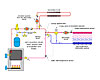
In a primary/secondary piping system, the secondary circuits “see” the primary loop as their expansion tank. The closely spaced tees that couple the secondary circuit to the primary loop become the PONPC for the secondary circuits. Thus, install circulators so they push water into the secondary circuit as shown in Figure 4.In systems with a hydraulic separator, the expansion tank can be placed almost anywhere in the vicinity of the hydraulic separator. I typically show it near one of the lower connections (e.g., system return or boiler return). Some hydraulic separators even have a tapping or extension near the bottom to which the expansion tank can connect. Although fine from a hydraulics standpoint, I urge you to install the tank so that sediment that may accumulate at the bottom of the hydraulic separator will not drop down onto the top of the expansion tank’s diaphragm. Use a tee and some elbows to offset the expansion tank as shown in Figure 5.
Pumping away means away from the point of no pressure change rather than away from the boiler. Use it on every installation and enjoy the benefits.
Links
Looking for a reprint of this article?
From high-res PDFs to custom plaques, order your copy today!


