Simplification
John Siegenthaler
Do you ever feel there are just too many pipes, circulators, controls and other gadgets in the hydronic systems you install? It’s amazing how a system shown on a well-organized schematic can sometimes turn into a dizzying array of hardware when it’s finally installed.
Many of us have seen “prize-winning” hydronic systems displayed in trade journals and other publications. Most of these systems are one-of-a-kind works of art. With proper design, documentation and scheduled maintenance, they can serve their owners well. Take away any of these requisites and you’ve got a very expensive collection of hardware that nobody seems to understand or wants to service. The latter scenario is a serious Achilles’ heal for our industry. The last thing we need is for mainstream consumers to think that hydronic heating has to be complex to be correct.
This month we’re going to look at ways of simplifying hydronic heating systems. The goal is to trim away at design details and hardware that doesn’t necessarily have to be part of the system for it to deliver efficient operation and superior comfort.
Less Multitemperature Systems
One decision that comes early in the planning of a hydronic system is whether or not that system requires multiple supply water temperatures. An example is a radiant panel system that warms a bare slab in the basement and also supplies heat to a staple-up tube-and-plate assembly on the first floor.By default, many designers specify a separate mixing device for each type of radiant panel construction. Even when the panel construction doesn’t change, some designers call for a separate mixing assembly for areas with different floor coverings (i.e., ceramic tile versus padded carpet). Sometimes a separate mixing assembly is also used on a floor-level basis, even when the water temperature requirements of the heat emitter on those floor levels are identical.
I’ve designed residential systems with three independent mixing assemblies and seen systems with at least six such assemblies. Do these systems work? Sure they do. Is this complexity necessary? Not necessarily.
Here’s a somewhat subjective but none-the-less rational criteria to help you decide if multiple water temperatures are needed:
1. Add up all the circuit supply water temperatures calculated for design load conditions.
2. Calculate the average of these supply temperatures.
3. If the supply temperature for a given circuit is more than 10 degrees F above or below the average temperature, identify it.
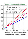
4. Consider modifying any identified “extreme” circuits through changes in tube spacing to increase or decrease their required supply water temperature at design load conditions. Try to bring that temperature within +/- 10 degrees F of the average temperature of all circuits. Remember to calculate a new average each time a circuit supply water temperature changes. In basements, consider tube spacing of 18 inches, or even 24 inches if floor surface temperature variations are not deemed a significant problem.
Here’s an example. Suppose you’re planning tubing for a bare concrete slab and need 20 Btu/hr/ft2 of heat output at design load conditions, with a corresponding indoor temperature of 70 degrees F. Based on Figure 1, at 12-inch tube spacing, the average circuit water temperature needs to be about 27 degrees F above the room air temperature (e.g., 27 + 70 = 97 degrees F). However, the same building also has a gypsum thin slab for the upper floor, and at design load these circuits need 112-degree F average water temperature. Increasing the tube spacing within the concrete slab portion of the system to 18 inches increases the average water temperature to about 104 degrees F.

In this situation, one might argue it’s better to decrease tube spacing on the higher temperature circuits and bring the average system water temperature down to promote efficiency gains at the heat source. This is certainly valid for systems using mod/con boilers, geothermal heat pumps or solar collectors as heat sources. Only a life-cycle cost comparison factoring in changes in heat source efficiency versus the higher installation cost of more tubing can provide a substantiated answer. When a conventional (noncondensing) boiler is used, changes in boiler efficiency are likely to be minimal, and cost savings will be largely derived by not installing multiple mixing assemblies.
5. If variations in tube spacing aren’t enough, discuss the possibility of different finish flooring with the client before giving up on the use of a single supply temperature.
I’ve found it possible to combine slab-on-grade systems with both thin slabs and even underfloor tube-and-plate systems in certain circumstances. Eliminating multiple mixing assemblies in these situations can reduce installation cost by hundreds of dollars.
When a single supply water temperature is possible, consider zoning on a manifold-by-manifold basis using zone valves. If zoning on a circuit-by-circuit level is necessary, you’ll need to use valve actuators on each circuit. Another possibility is to mix in nonelectric thermostatic valves for zone control.
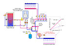
Any of these approaches allows for a simple delivery system using a single variable-speed pressure-regulated circulator. An example of such a system using a mod/con boiler is shown in Figure 2.
When two simultaneous supply temperatures are needed, consider using proportional reset control with a manually set “dumb” mixing valve. An example is shown in Figure 3.
The dumb mixing valve does not have a thermostatic or motorized actuator. It simply maintains a set mixing ratio between the entering hot and cool streams. When the temperature of the hot stream varies based on outdoor reset (as it would from a mod/con boiler), the outlet temperature from the dumb mixing valve will also vary along a shallower reset line as shown in Figure 2.
Keep in mind that proportional reset requires a circulator on the load side of the mixing valve. Furthermore, it’s not advised for zones that must recover quickly from setback conditions or will be subject to frequent changes in thermostat settings or internal heat gains. That’s because a “dumb” mixing device can’t respond to such changes as quickly as a “smart” mixing assembly that’s constantly correcting for deviations in its supply water temperature. For an in-depth discussion of proportional reset, see the Hydronics Workshop columns from May 1999 and June 2004 (available in our Archives section; free site registration required).
Less Zones
The ability to divide a heating system into several independently controlled zones is one of the most salient benefits of hydronics. There are several techniques for providing two to six zones in almost any modern hydronic system. This can usually be done at a significantly lower cost than an equal number of zones in a forced-air system.However, just because you can set up every room in a building as a separate heating zone doesn’t mean you should. This is especially true when installing wired zone controls. By the time all the transformers, valve actuators, relay centers and thermostats are connected, you may have installed a couple miles of low-voltage cable. It’s time-consuming work with a lot of added parts that can easily add a couple thousand dollars to the installed cost.
Even when money isn’t an issue, those room thermostats might only be used to balance heat flow within the building rather than for frequent temperature adjustments. Balancing can usually be done by circuit flow adjustments at the manifold. Besides, what homeowner wants to go around replacing the batteries in all those stats every year?
In keeping with the theme of simplification, it’s important not to “over-zone.” When selecting zones, look for open areas within a building. Such areas “communicate” as far as heating is concerned, and seldom need to be on separate zones. Also, look for areas that receive significant solar heat gain and put them on separate zones from nonsolar gain areas.
Room-by-room zoning is advisable in buildings where doors to rooms are frequently shut, and those rooms are subject to significant differences in either air infiltration or internal heat gain. Such “compartmentalized” buildings are a tough case because there’s minimal thermal interaction between rooms. The case for room-by-room zoning in such buildings is further strengthened when the people occupying those rooms may have widely different preferences on indoor comfort temperature. Keeping the peace usually means a thermostat in every room.
If you need room-by-room comfort control, take a good look at nonelectric thermostatic control valves. They’re available for baseboard and panel radiator systems as well as mounted in wall-mounted boxes for site-built radiant panel systems. No wires and fully modulating control. Some manufacturers even offer battery-powered automatic setback actuators if needed.
Less Transformers
Ever been in a mechanical room where there are four or five control transformers buzzing away 24/7? Put your hand on them and they feel warm. That’s because they’re sitting there converting electricity into heat through their primary windings regardless of whether there is an active load on their secondary winding - like a pilot light for low voltage. To minimize standby losses, use control arrangements that turn off transformers when the portion of the system they serve is not operating (i.e., don't let the transformer(s) in a cooling system operate during the heating season and vice versa).Multiple transformers also set the stage for potential problems if connected in parallel (intentionally or inadvertently) without proper “phasing.”
The cost of installing multiple transformers is obviously more than the transformers themselves. Each needs a J-box, mounting plate, wiring, conduit connectors, wall space and time to put it all together. Although the savings your customer will realize due to reduced use of control transformers is probably not going to determine if their mortgage gets paid, every little bit helps.
Less Adapter Fittings
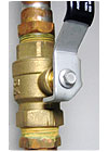
I used to think of a box full of fittings and valves as incidental to the overall hardware cost for a hydronic system. That changed when copper fittings started being delivered in Brinks trucks.I recently looked up the estimated installed cost of a 3/4-inch MxC copper adapter fitting in the 2006 RS Means Mechanical Cost Data book. With overhead and profit, Means estimates the installed cost at $32 each. According to Means, that adds $64 to the cost of installing a 3/4-inch zone valve you may have nonchalantly purchased with FPT connections. Same for the 3/4-inch FxF ball valve shown in Figure 4. My advice is to get away from installing threaded adapter fittings whenever possible. This could trim a box full of copper fittings out of your next system. Need I say more?
Less Antifreeze
I have a saying about antifreeze - “The only good thing about antifreeze it that it doesn’t freeze.”Think about it: Glycol-based antifreeze decreases the heat capacity of the fluid relative to water. This requires increased flow rate for the same heat conveyance. The higher viscosity of glycol-based antifreeze also adds significantly to head loss. At 120 degrees F, a 50 percent solution of propylene glycol increases head loss (at the same flow rate) by about 24 percent. When the flow rate is increased to compensate for reduced heat capacitance, the head loss goes up by 47 percent! That translates into more pumping power and higher operating cost.As many of you have discovered, glycol-based antifreeze also has a propensity to weep through threaded fitting joints and create surface oxidation where water would either not leak or quickly evaporate without scaling.
Oh, I almost forgot to mention that in addition to the above attributes, filling a system with a 50 percent glycol solution can easily add a few hundred bucks to installed cost.
So, where should antifreeze be used? Well, snowmelting systems and closed-loop solar collectors obviously need the protection it offers. In Northern climates, we also specify glycol in residential garage heating circuits, and in homes that will be unoccupied for several consecutive winter days.
We used to specify antifreeze for floor heating systems in large slab-on-grade facilities such as highway garages. However, many of these buildings now have emergency generators that can keep the heating system running during a prolonged power outage. With constant circulation “stirring” heat around in a large concrete slab, it could take several cold days before water in the slab circuits would be in danger of freezing, even if the boiler was not operating. Given these favorable odds, we now avoid antifreeze in this type of facility.
Less Circulators
If you’ve been following this column for the last couple of years, you’re not surprised to see circulators on the pruning list.There was a time when most residential hydronic systems had one to perhaps three circulators. We now find one to three describing the rows of circulators along the mechanical room wall. This happened because small wet-rotor circulators became very cost-competitive with zone valves, electricity was still relatively cheap, and a row of neatly aligned circulators looks like a row of merit badges to other Wet Heads.
Systems with rows of circulators work, but at the expense of far higher electrical operating cost relative to alternatives now available. It’s time to recognize that this no longer represents the state-of-the-art in hydronic heating design.
Over time, our industry has accepted change in other methods and materials. Examples include mod/con boilers, microbubble air separators, injection mixing, electronic thermostats and PEX tubing. Many hydronic pros using these “modern” methods and materials already have sensed the changing tide regarding over-pumping. They’re responding by taking advantage of concepts that use a fraction of the circulation energy their earlier systems required. I’d like to be counted among them.
As time passes, more designers will realize that low-power circulation systems using ECM-based circulators are working well for the “early adapters,” and the rolling snowball will continue to grow.
Why Less Is More
It’s always a bit precarious to write about removing hardware from systems. That hardware produces income for its manufacturer right down to the professional who installs it. Believe me, it’s nothing about reducing that income that prompts me to discuss these topics. Instead, it’s about ensuring that average consumers can view hydronic heating as an affordable, efficient and understandable technology, something they want in their home or place of business.That goal necessitates periodic self-examination of what we do as individual professionals, and as an industry. We want to increase market share, not parts count. Why build the space shuttle when our clients need a Cessna?
Looking for a reprint of this article?
From high-res PDFs to custom plaques, order your copy today!