The Long Way Around
John Siegenthaler, PE

One of the classic blunders of hydronic design is to create excessively long series piping circuits. Over the years, I've noticed that many new designers have a predisposition to connect devices like radiators, boilers, valves and piping into series circuits. There's something fundamentally appealing about making an “unbroken chain” out of such components. Unfortunately, this can quickly lead to problems with both thermal and hydraulic performance.
One recurring example is to unroll a 1,000-ft. coil of 1/2-inch PEX tubing into a single floor heating circuit. I've had inquiries on two such installations within the last year. The person doing the design was probably thinking that long circuits reduce on the number of manifold connections required. Perhaps they even reasoned that manufacturers would not sell tubing in 1,000-ft. lengths if 1,000-ft. circuits were not feasible.

How Bad Is The Blockage?
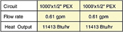
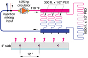
It's hard to generalize on where a 1,000-ft. long floor heating circuit might occur. One possibility is that it's one of several circuits on a manifold where the other circuits have reasonable length. Perhaps the designer used a single long circuit to cover the entire floor area in a large great room, while smaller rooms got shorter circuits. Another possibility is that two or more excessively long circuits could be supplied from the same manifold.To get a handle on the flow and heat transfer in such situations, I used the Hydronics Design Studio software to simulate two scenarios. The first was a four-circuit manifold serving three circuits of 1/2-inch PEX tubing each 300-ft. long, with a forth circuit of 1/2-inch PEX that's 1,000-ft. long (see Figure 1). All circuits are installed 12 inches on center in a bare 4-inch thick concrete slab, and supplied with 110 degree F water. The room temperature was 70 degrees F. Manifold flow was provided by a typical 1/25 horsepower zone circulator.
Here are the calculated flows and heat outputs for this scenario:
Some of you may be looking at the heat output of 10,741 Btu/hr. for the 1,000-ft. circuit and thinking that's more heat output than from the 300-ft. circuits.
The second scenario simulated was a system with two 1,000-ft. circuits of 1/2-inch PEX with the same installation and operating assumptions as the first case. Here are the results for flow and heat output:
Again, each circuit would serve about 1,000 square feet of floor area and only produce an upward heat output of about 11.4 btu/hr./ft2. That's quite low for a bare slab supplied with 110-degree F water.
These 1,000-ft. circuits are operating with ∆Ts in the range of 34 degrees F to 54 degrees F. That's two to three times higher than normal. Although the supply water temperatures and flow rates are reasonable, the upward heat outputs are low for the supply water temperatures used. Such circuits also will produce very noticeable variations in floor surface temperature. The floor will feel warm above the inlet of the circuit and almost as if unheated near the other end. Trust me, people do notice this and will justifiably complain about it.

Back And Forth
So how might you correct a situation where someone installed say a 1,000-ft. circuit of 1/2-inch PEX tubing in a concrete slab floor?If the path of the circuit is known, one could certainly take the jackhammer approach to exhume the tubing at select locations and divide the system into multiple shorter circuits. Although this might be possible, it's a pretty messy approach.
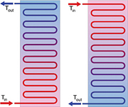
A much less invasive technique is to periodically reverse the flow direction through the circuit. Each end of the circuit shares an equal amount of time with the warmest and coolest fluid in the circuit. The concept is shown in Figure 2.
The schematic in Figure 3 shows how the four-way valve could be piped along with a single circulator to reverse flow through the distribution system. It acts similar to a refrigerant reversing valve in a heat pump.
The four-way valve only stops at the extreme positions of its operating range. We'll refer to them as the 0- and 90-degree positions.
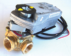
The device that rotates the valve's stem is a two-position motorized actuator.
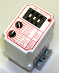
The logic that directs the actuator to repeatedly power on and off is supplied by a time delay relay set to a repeat cycle mode. An example of one such device is shown in Figure 5. With the selector switch set to “repeat,” this relay will open and close the contacts to the actuator every time a set time delay has elapsed. Such relays can operate over a wide range of time delay periods. For hydronic heating systems, cycle times of 15 to 30 minutes are probably appropriate. Shorter cycles will increase actuator wear, and longer cycles could lead to unacceptable variations in room temperature. More research is needed on the optimal cycle times for flow reversal. I'll keep you posted.
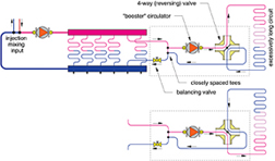
The original long circuit is “cropped” to form a primary loop of sorts. This short section of pipe supplies a pair of closely spaced tees that lead through the booster circulator and four-way reversing valve. These tees effectively isolate the booster circulator, four-way valve and the remainder of the long circuit from the pressure dynamics in the manifold. This prevents interference with the other manifold circuits. The balancing valve in the short section of tubing adds flow resistance to prevent the short segment of pipe from stealing flow from the other manifold circuits.
The concept of periodic flow reversal is relatively new to me. While researching it as a means of correcting long circuit problems, it became apparent that this concept can also yield desirable operating characteristics in new hydronic installations. I would even venture to say it might become a common design concept in future North American hydronic systems. Later this year we'll look at how to use it in more detail.
Looking for a reprint of this article?
From high-res PDFs to custom plaques, order your copy today!


.jpg")