A Signature System
John Siegenthaler
Over the last few years, I've had the opportunity of presenting many training seminars on modern hydronic heating all over North America. Along the way, I've met many people who are eager to learn and apply new concepts. True professionals who realize that hydronics is more than just a job, it's a "practice" like law or medicine. As such, it requires a constant investment in learning.
The payback for such learning can be almost instantaneous. Even a small piping or wiring detail incorporated into one system can return the learning cost as reduced installation time, better performance, higher reliability, or maybe all three. That detail goes on to pay additional dividends every time it's used in another system. True professionals look for such incremental improvements on every system they design or install.
One such professional is Mike Reif of Reif's Hammers and Pipes in Sitka, Alaska. Here's a guy who takes hydronic heating as seriously as fishing (and when you live in coastal Alaska that's no trivial statement).
I met Mike while presenting an RPA Radiant Precision seminar in Juneau last year. The seminar discussed many contemporary hydronic design concepts, such as parallel primary loops, injection mixing, buffer tanks and proportional reset control. Each of these concepts, when properly deployed, can improve performance, lower cost, and in many cases improve the life expectancy of a system. Each can be applied individually, or in some cases combined into a single system.
Mike used the information presented in the seminar to develop a "signature system" for his company. He was after a system versatile enough to handle both large and small jobs; one that could deliver optimal comfort from both high- and low-temperature heat emitters. Most importantly, he was looking for a system that would provide a consistent approach to piping and wiring from one job to the next.

The 'Inside Out' Tank
A concept schematic for Mike's system is shown in Figure 1.A single oil-fired boiler serves as the heat source. It's piped as a secondary circuit into a primary circuit that passes through a Turbomax indirect water heater. Unlike a conventional indirect water heater, this tank holds domestic water in a coiled copper heat exchanger rather than the tank shell. The domestic water is heated as it passes through the coil.
A tempering valve ensures the water is reduced to 130 degrees F before heading out to the fixtures. In a way, the concept is similar to that of a "tankless coil" mounted in a boiler. However, the larger surface area of the heat exchanger, the high thermal mass of the tank, and the well-insulated jacket deliver far better efficiency and temperature stability.
A setpoint control fires the boiler as necessary to maintain the tank water between upper and lower limits at all times. Mike's system uses a range of 160 degrees F to 180 degrees F. Different temperature limits are possible depending on the supply temperature needs of the space heating system and the minimum allowable boiler inlet temperature. The wider the "cycling range" of the tank, the fewer and longer the boiler cycles become.
The fact that the tank stores "boiler water" rather than domestic water allows it to serve as a buffer tank for the space heating system. This is especially important when the space heating system is divided up into several independently controlled load and zones.
When a load calls for heat, the primary circulator is turned on to move tank water around the primary loop. The boiler is not fired until the tank's temperature drops to the lower-limit setting of the setpoint control. This allows the system to deliver heat to "micro-loads," such as a towel warmer, without short cycling the boiler.
The boiler's primary/secondary piping prevents the boiler's heat exchanger from serving as a heat dissipater when the burner is off and heat is being supplied from the buffer tank. Each time the burner fires, it remains on for several minutes while the buffer tank is recharged to its upper-temperature limit. Any load that's calling for heat at the time further lengthens the boiler's on-cycle.
Primary Lineup
A secondary header system connected to the primary loop supplies high-temperature heat emitters such as baseboard, unit heaters or air handlers. Because it's the first secondary load along the primary circuit, it receives the highest available water temperature. Furthermore, each circuit supplied from the header receives water at the same temperature.Farther downstream, the primary loop supplies a variable speed injection mixing assembly that meters heat into an intermediate temperature "utility loop." At design load conditions, the water temperature on the supply side of this loop is about 140 degrees F.
As outdoor temperature increases, the injection control reduces the temperature of this loop. Full reset of supply temperature is possible since any cool water returns to the buffer tank rather than directly to the boiler. The injection control also monitors boiler inlet temperature and reduces the speed of the injection pump when necessary to prevent sustained flue gas condensation during cold starts or recovery from temperature setbacks.
One load connected to the utility loop is an intermediate temperature floor heating subsystem. In this case it supplies tube-and-plate underfloor heating. This intermediate water temperature is also well suited for panel radiators or radiant ceiling panels.
Who knows, the next time Mike deploys this system, these may be the heat emitters selected.

Parallelism
A photo of the utility loop is shown in Figure 2. Technically this piping constitutes a parallel primary loop. It contains three crossover bridges, each with a balancing valve. A pair of closely spaced tees is the take off point for each secondary circuit supplied by the utility loop.This configuration allows each secondary circuit to be supplied with the same water temperature. This is especially important because the water temperature in this loop is being fully reset. The closely spaced tees also eliminate interference between various secondary pumps. The number of crossovers in the parallel primary loop can be changed depending on the number of secondary loads required.
The balancing valves in the crossovers allow the flow to be proportioned to the size of the secondary loads. If 80 percent of the load is supplied from one of the three crossovers, that crossover should carry about 80 percent of the total primary loop flow. Mike installed ISTEC balancing valves with integral flow meters to quickly establish the proper flow proportions.

Last But Not Least
To reduce the water temperature to an appropriate level for the low-temperature floor heating, Mike used a manually set (nonmotorized) three-way valve to create proportional reset. The "hot" water input to this valve comes from the utility loop. The cool water comes from the return side of the floor circuits.The valve is set to mix 140-degree F water with 90-degree F return water to provide 105-degree F water to the floor circuits. Figure 3 is a close-up showing the two three-way valves. Note the differential pressure bypass valve on the low piping loop, which supplies a manifold equipped with individually controlled valve actuators.
As the injection control reduces the temperature of the utility loop, the temperature supplied to the low-temperature circuits also decreases proportionally. The reduced water temperature allows nearly constant circulation in the floor circuits, and thus consistent comfort without the need for a second or third mixing control.
If necessary, the two proportional mixing subsystems could be set to deliver different water temperatures at design load conditions. One might supply 120-degree F water to a carpeted floor area, while the other supplies 100-degree F water to a bare basement floor slab. Thus, this system is capable of supplying four different water temperatures (one nonreset temperature from the primary loop, and three fully reset temperatures from the utility loop). It does so using only one low-cost injecting mixing control.
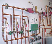
Figure 4 shows the overall system installed in a very neatly executed mechanical room.
Mike's approach demonstrates what creative hydronic heating professionals can do when new information is combined with the desire to provide the best value and performance to their clients.
The photos in the June Hydronics Workshop column were taken by Mike Reif.
Looking for a reprint of this article?
From high-res PDFs to custom plaques, order your copy today!