Editor’s note: This is the first in a two-part series on cordwood gasification boiler systems.
Modern gasification boilers are the ultimate way to burn cordwood. When properly installed and operated, these boilers can reach steady-state combustion efficiencies exceeding 80% and full-cycle efficiencies (which includes the start-up and burn-out phases) in the range of 65-75%. Contrast that with the typical full-cycle efficiencies of single-stage outdoor wood furnaces that struggle to reach 40%.
Furthermore, cordwood gasification boilers only emit about 2-3% of the particulate emissions (known as PM2.5) compared with single stage outdoor wood furnaces.
The key to high thermal efficiency and low emissions is operating the cordwood gasification boiler at “full throttle.” Once a fire is kindled, the upper combustion chamber is fully loaded with dry cordwood and a blower is turned on to force combustion gases downward.
At this point, the temperature in the upper combustion chamber is sufficient to chemically change solid wood into pyrolytic gases (this is known as gasification). Those gases are forced through a slot in a ceramic plate at the bottom of the chamber, and combined with a stream of hot air.
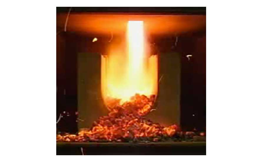
The resulting secondary combustion looks and sounds like a blow torch, and can reach temperatures of more than 2,000° F. Figure 1 shows what that combustion process looks like in the boiler’s lower chamber.
The super-hot combustion products pass from the lower chamber through steel fire tubes where heat is transferred to water.
A typical “batch burn” cycle lasts three to four hours. During that time, the boiler almost always generates more heat than the building needs. The solution to this mismatch is thermal storage — and lots of it.
A guideline for thermal storage is 130 gallons of water per cubic foot of primary combustion chamber volume. A typical cordwood gasification boiler rated at about 170,000 Btu/h peak output would have a primary combustion chamber volume in the range of 6 to 8 cubic feet. Based on this guideline, that boiler would require 780 to 1,040 gallons of thermal storage.
Storage tanks with these volumes are available in either pressure-rated or non-pressurized designs. The pressure-rated tanks are typically fabricated to ASME pressure vessel standards using welded steel. Functionally, they meet the need, but logistically, they’re large, heavy and expensive.
Non-pressurized tanks are supplied in “knock down” form. This allows the components that are eventually assembled to build the tank to pass through standard doorways, down stairs, etc. Non-pressurized tanks combine a panelized insulated shell that provides structure with a drop-in liner made of EPDM rubber or polypropylene. Typical upper temperature limits for these liners are in the range of 175°.
Although my personal preference is for closed pressure-rated tanks, and thus no need for heat exchangers, the reality is that such tanks are not easy to install in a typical residential basement. Knock-down style non-pressurized thermal storage tanks have their place.
How we’ve always done it
A traditional approach to integrating a cordwood gasification boiler, or other closed-loop heat source, to a non-pressured thermal storage tank and then connecting back to a closed-loop hydronic distribution system is shown in Figure 2.
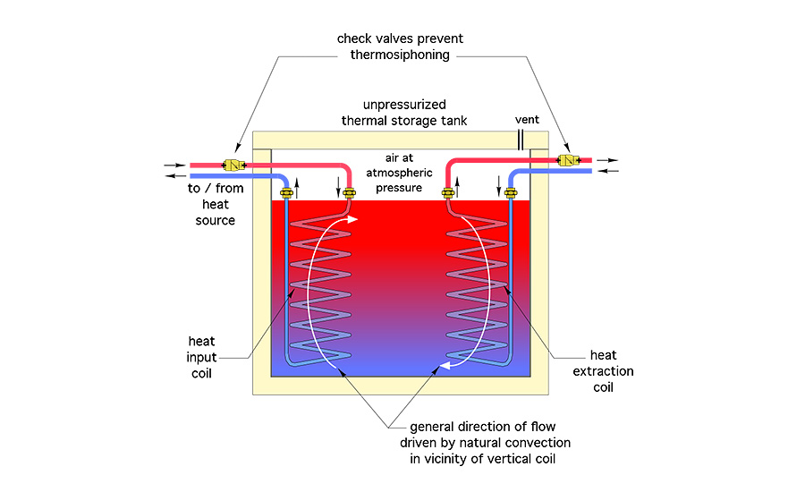
The cordwood gasification boiler or other heat source is connected to a copper coil heat exchanger suspended inside the tank. This forms a closed hydronic system. Similarly, the distribution system is supplied from a second coil heat exchanger within the tank. This forms another completely isolated closed hydronic system.
However, the thermal storage tank is an open hydronic system that is vented directly to the atmosphere. With this arrangement, heat passes from a closed system to an open system and back to a closed system. The two coils with the thermal storage tank are the dividing points between these subsystems.
Because they are isolated from each other, both closed-loop subsystems need all the usual “trim,” including expansion tanks, pressure relief valves, make-up water components, air separators, and purging valves.
Whenever heat passes through a heat exchanger, there is a “temperature penalty.” The fluid giving up the heat must be hotter than the fluid receiving the heat. How much hotter depends on the size and effectiveness of the heat exchanger.
When two heat exchangers are in series with the path of heat flow, these temperature penalties add together. They combine to widen the gap between the water temperature available from the heat source and water temperature available to the load. That’s not good from the standpoint of thermodynamics.
Coil heat exchangers operate with forced convection within the tubing, and natural convection on the outer surface of the tubing. The latter is a much “weaker” form of heat transfer due to the relatively slow buoyancy-driven fluid velocity along the outer surface of the coil.
The surface area of a coil heat exchanger usually has to be large to compensate for this weaker convection effect. Large copper coil heat exchangers are expensive. One supplier offers a ¾-inch tube size copper coil with 120 feet of tubing for a list price of just over $1,000. 180-foot-long coils of the same tube size list for more than $1,400.
It has also been a challenge to get usable heat exchange performance data for some coil suppliers. For example: How large must the coil heat exchanger be to sink 170,000 Btu/h from a cordwood gasification boiler operating at full throttle, and producing 185° water, when the tank water is 170° at the top and 160° at the bottom? I’ve not been able to find published data to answer that question. Considering what these coils cost, designers need good sizing information to avoid driving the cost of an already premium priced heating system needlessly higher by oversizing the coils.
Another factor to consider is that coil heat exchangers must be mounted within the tank. That requires proper piping supports. It also means that any repairs to the coil or supporting piping will require the top of the tank to be removed. It may also be necessary to partially or fully drain the tank to service the coils. Possible, but not fun.
Put it outside the tank
An alternative is to use a brazed-plate stainless steel heat exchanger mounted outside the tank. With the right design, this eliminates both coils inside the tank. It also eliminates one of the two temperature penalties associated with having two heat exchangers in the path between the heat source and the load.
Figure 3 shows one way to set up a single external heat exchanger for interfacing a non-pressurized thermal storage tank to a pressurized, closed-loop, balance-of-system.
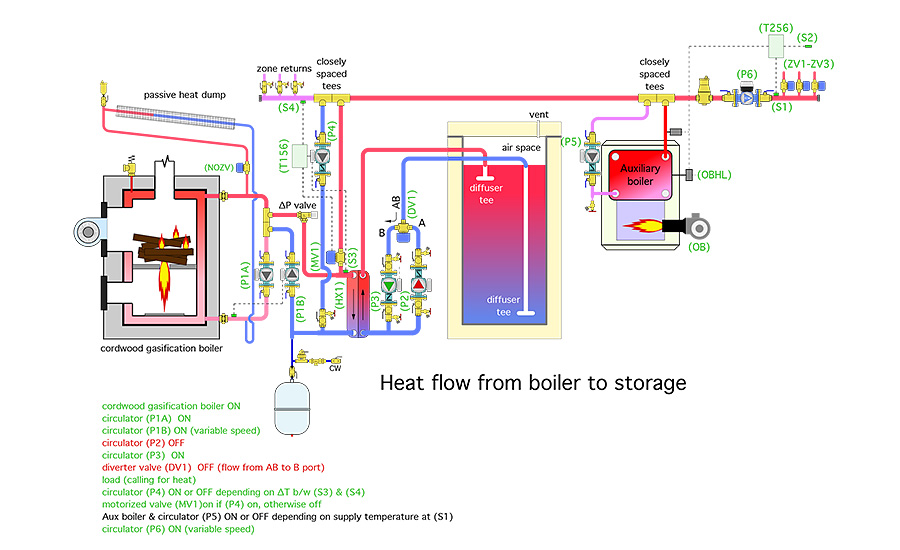
As shown, heat generated by the cordwood gasification is being shuttled to the distribution system via circulator (P4) or passed through the heat exchanger to thermal storage. Any flow from the boiler that doesn’t go to the distribution system passes into the left side of the heat exchanger. Circulator (P2) is operating to create flow through the right side of the heat exchanger. That flow absorbs heat and carries it to the thermal storage tank.
This design allows the hottest water from the cordwood gasification boiler to be “injected” into the distribution system rather than requiring that heat to pass through both coil heating exchangers and interact with the large thermal mass of the storage tank. That can be a significant advantage when the tank temperature is low and heat is immediately needed by the load.
Circulator (P4) can be turned on whenever one or more zones is active and off at other times. It could also be controlled as a variable-speed injection circulator. The latter would ramp the circulator speed up and down in an attempt to maintain a target supply water temperature to the distribution system. That target temperature could be a fixed set point or based on outdoor reset control.
The heat exchanger should be selected with a relatively low pressure drop — under 1 psi at full flow from the boiler. This provides some degree of hydraulic separation between circulator (P1B) and (P4). Still, 1 psi is more than the opening pressure of a typical check valve cartridge in a wet rotor circulator. Left “unchecked” the nominal 1 psi pressure differential across the heat exchanger would drive flow upward into the distribution system even when circulator (P4) is off.
One remedy is a zone valve or motorized ball valve with spring return actuator installed in the riser piping between the heat exchanger and distribution system, as shown in Figure 3. This valve opens when circulator (P4) is on, and closes whenever (P4) is off. When closed, it prevents any hot water from passing upward into the distribution system when there is no active load.
Discharging the “thermal battery”
By the end of a typical “batch burn,” the thermal storage tank has absorbed a lot of heat. It’s at an elevated temperature and ready to supply the load for several hours, or maybe even a couple of days if outdoor temperatures are mild.
Figure 4 shows how heat flows from thermal storage to the load when the cordwood gasification boiler is off.
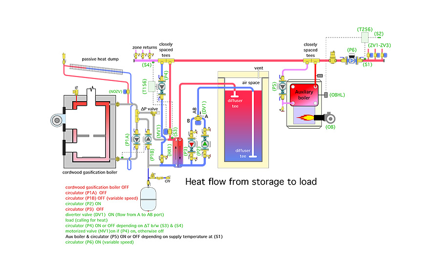
In this mode, the flow directions though both sides of the heat exchanger have reversed, as has the direction of heat flow across the heat exchanger. Hot water from the top of the thermal storage tank flows downward through the right side of the heat exchanger, passing heat to the left side and on to the load through circulator (P4). The forward opening resistance of the ∆P valve above circulator (P1B) prevents flow returning from the load from partially bypassing the heat exchanger.
The auxiliary boiler stands ready to either supplement the output from the cordwood gasification boiler, or replace it when necessary. It’s connected to the distribution system using a pair of closely spaced tees. That detail, in combination with the spring check in circulator (P5), prevents flow through the auxiliary boiler when it’s off.
The passive heat dump seen above the cordwood gasification boiler stands ready to dissipate residual heat from the boiler if a fire is burning and utility power is lost. The normally open zone valve (NOZV), which is closed whenever utility power is available, opens to allow thermosiphon flow between the boiler and an array of finned-tube elements mounted above the height of the boiler and with a slight slope to ensure air can be vented at the high point.
More to follow
A simplified piping system deserves an equally simplified control system. Fortunately that’s easy to accomplish with this design. I’ll show it — and explain it — in next month’s column.
This article was originally titled “Two into one” in the April 2018 print edition of Plumbing & Mechanical.
To read Siegenthaler’s article “Designing cordwood gasification boiler” in pdf form, please see here.


