
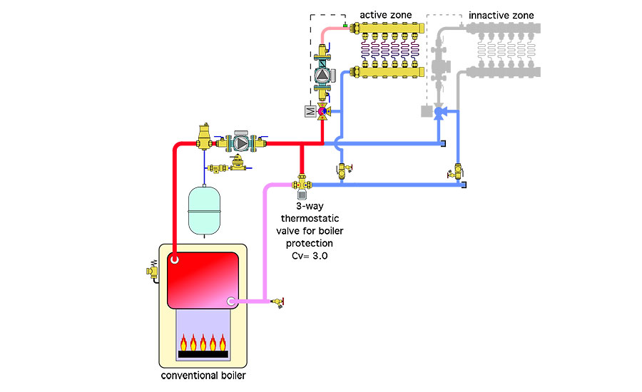
The Glitch:
An installer is asked to design a two zone radiant panel heating system. Due to panel construction, two independently controlled water temperatures are necessary. These will be achieved with two independently operating motorized 3-way mixing valves and their associated electronic controllers. A thermostatic mixing valve with a Cv of 3.0 will be used to boost the inlet water temperature to the cast-iron gas-fired boiler to 130 ºF to avoid sustained flue gas condensation. A schematic for the as-installed system is shown below. Can you spot several details that will lead to problems? How would you design the system differently?
The fix:
There are several problems with this layout.
-
Whenever multiple 3-way mixing valves are piped in parallel from a common header system, there must be a check valve on the return side of each sub-circuit just upstream from the purging valve. Without these check valves there can be flow reversal because the 3-way doesn’t necessarily block flow between its “hot” and “cool” ports. This is especially true of motorized 3-way valves that are simply powered down when the zone they supply is not calling for heat.
-
Look close, the purge valve on the right side sub-circuit is installed backwards.
-
Look even closer, the pressure reducing valve is installed backward. The pressure reducing valve and backflow preventer should also be flipped in position (e.g. backflow preventer upstream of pressure reducing valve). There’s also no shut off on the feed water system. Not a problem until one of those downstream valves needs service.
-
There is no need for hydraulic separation between the circulator near the boiler and the two zone circulators. Assuming the boiler circulator operates when either zone calls for heat, it will push flow into both zones.
-
The position of the boiler circulator is really close to the outlet of the air separator. Always keep a minimum of 10 pipe diameter of straight pipe upstream of all circulator inlets.
-
The three way thermostatic mixing valve, with the stated Cv of 3.0 is going to be a real choke point for flow. If the boiler is to be protected in this manner it’s important to use a valve with a Cv in the range of the flow rate through the boiler when all zones are operating.
These shortcomings have been corrected in the “fix” drawing below.
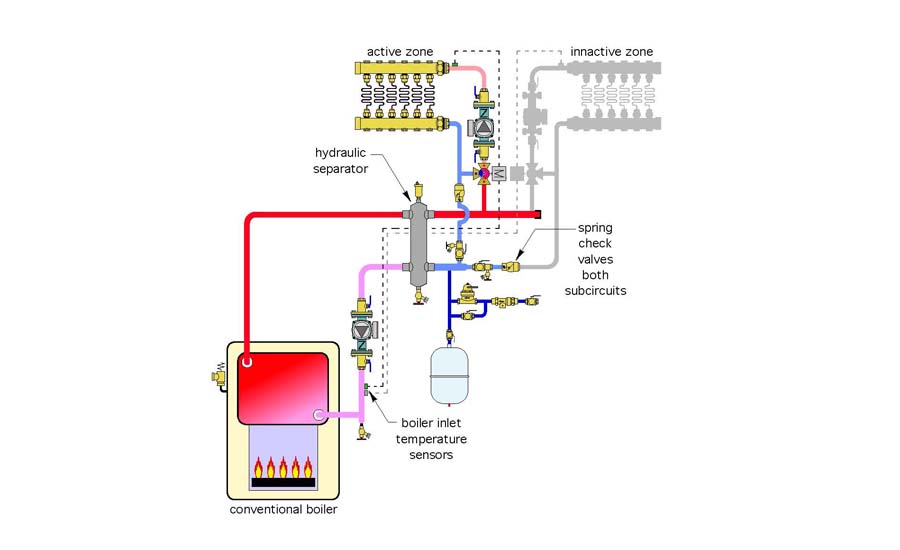
The fix drawing uses a hydraulic separator between the “boiler loop” and the two distribution sub-circuits. The upper portion of the hydraulic separator provides high performance air separation and thus eliminates the need for the air separator in the original design. The bottom of the hydraulic separator adds efficient dirt separation.
A spring loaded check valve has been added to the return side of each sub-circuit to prevent flow reversal when one zone is on and the other is off.
Most controllers designed to operate 3-way motorized mixing valves have a boiler “anti-condensation” function. When this type of controller is equipped with a temperature sensor mounted at the boiler inlet, it can reduce hot water flow into the hot port of the mixing valve so that the boiler inlet temperature quickly climbs and remains above the dewpoint of the exhaust gases (typically about 130 ºF). Taking advantage of this feature eliminates the need for a thermostatic mixing valve and simplifies the system. The boiler sensor is usually “in the box” with the mixing valve controller - use it.
The make up water assembly has been moved to allow for efficient system purging. This location also keeps the tank shell slightly cooler than when the tank is on the supply side of the boiler.
A bypass ball valve has been added to the make-up water assembly to allow maximum flow into the system during purging.
Another ball valve has been added to isolation the expansion tank for service or replacement without draining the system.


