The Glitch
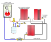
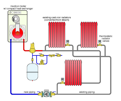
An installer decides to replace an old cast-iron boiler with a modern mod/con unit that has a 5:1 turndown ratio and integral outdoor reset control. He pipes in the new boiler to the existing black-iron piping system as shown below. He also installs thermostatic radiator valves on the return side of each radiator to provide room-by-room zone control.
Can you spot some potential problems in the making?
The Fix
One error in the original design is the circulator placement. It’s pumping toward the connection point of the expansion tank. This results in a drop in pressure between that point and the inlet of the circulator. It may even be possible that the pressure in this portion of the system goes subatmospheric when the circulator is operating. This is an invitation for air to enter the system.
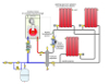
The thermostatic radiator valves should be installed on the supply side of the radiators. This helps prevent heat migration from the supply piping into the radiators. The valves shown have angle pattern bodies. This keeps the thermostatic head far enough from the radiator to minimize convective interference that could cause erratic operation of the valve.
Manually-operated air vents are shown at the top of each radiator to aid in purging the system.
Anytime new hardware is added to an older system, especially a system with iron or steel piping, it’s a good practice to install a means of dirt separation. In this case, a hydraulic separator is used to provide that dirt separation. It also provides hydraulic separation between the boiler circulator and variable-speed distribution circulator, and high-performance air separation. Because of this “triple function” capability, a hydraulic separator is an ideal device to interface old with new.
A purging valve has been installed on the inlet of the hydraulic separator to allow for adequate forced-water purging of the distribution system and initial dirt removal. Initial flushing should use a surfactant to help cleanse the old piping components and radiators. Another purging valve has been added on the outlet piping from the boiler to ensure that the boiler circuit can be properly flushed of air during commissioning.
An ECM-based variable-speed, pressure-regulated circulator is shown in the distribution system. This circulator will vary its speed as needed to maintain proportional differential pressure across the distribution system as the thermostatic radiator valves open, close and modulate.
Finally, a supply temperature sensor that regulates boiler modulation is shown on the supply side of the distribution system (downstream of the hydraulic separator). This allows the boiler to modulate based on the true water supply temperature to the radiators.


