Over the last few years, hydraulic separators have been gaining popularity in the North American hydronics market. Eager to keep up with this new technology, an installer decides to install a hydraulic separator between a boiler and distribution system.

The Glitch
Over the last few years, hydraulic separators have been gaining popularity in the North American hydronics market. They provide an alternative to closely spaced tees when the task is to isolate the pressure dynamics of one hydronic circuit from those of another, connected circuit.
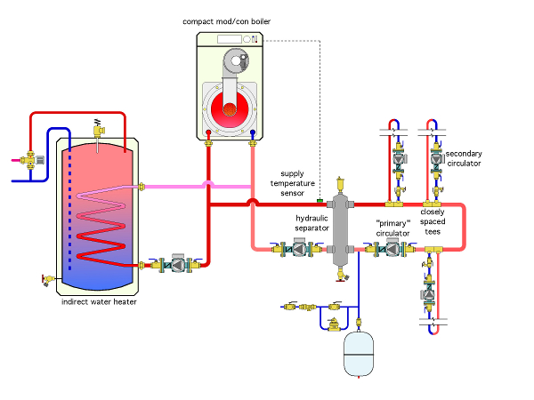
Eager to keep up with this new technology, an installer decides to install a hydraulic separator between a boiler and distribution system as shown in the figure below. This system serves space-heating loads and a prioritized indirect water heater.
Look over the drawing and see if you can spot any errors, as well as methods of achieving the desired operation with simpler piping and less hardware.

The Fix
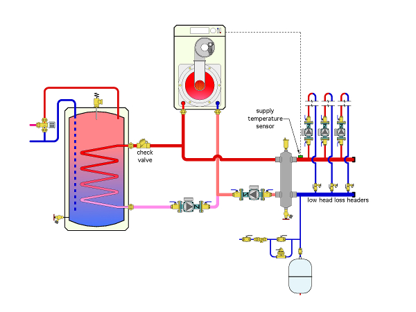
A hydraulic separator eliminates the need to use closely spaced tees when connecting load circuits. There is absolutely no need to create an extra pumped loop on the load side of the hydraulic separator. All load circuits can be piped across the headers as shown. Those headers should be short and sized for a maximum flow velocity of 2 ft. per second. This keeps the pressure drop along the length of the header extremely small (e.g., negligible).
The slow flow rate along the vertical height of the hydraulic separator adds virtually nothing to this pressure drop. Thus, the differential pressure between the upper and lower headers is essentially zero. Each load connected across the headers is unable to detect the presence of the other load circuits.
Other errors in the original drawing include:
Without the additional check valve at the upper connection, there will be a slight but “aggravating” flow of hot water along the top of the pipe while cool water slides back along the bottom of the pipe. The larger the pipe, the more pronounced this effect. Why let this effect slowly suck heat out of the tank?


