The Glitch
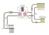
A contractor connects an on/off water-to-water heat pump to a highly zoned radiant floor heating system as shown below. He was told that there is no need for an expansion tank in the earth loop because the HDPE piping has enough “give” to accommodate the expansion and contraction of the earth loop fluid. Thus, the contractor assumes he can use this to his advantage on the load side of the heat pump.
He pipes up the radiant floor manifold with leftover pieces of HDPE pipe and forgoes the expansion tank. He uses two cast-iron zone circulators, one to supply each manifold station. The zoning is done using manifold valve actuators to control flow in each circuit.
Can you spot several problems with this design and installation?
The Fix
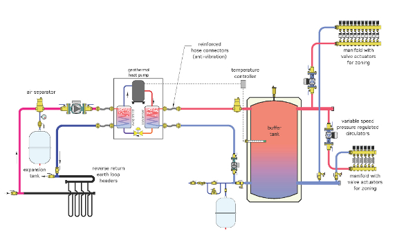
Although HDPE pipe does expand and contract, this only partially compensates for the lack of an expansion tank. There will still be wide pressure fluctuations in earth loops that rely solely on the expansion and contraction of the earth loop piping. A better approach is to install an expansion tank. While you’re at it, install a microbubble air separator to help rid the earth loop of dissolved air over time. Why shouldn’t earth loops “enjoy” the same highly deareated and pressure controlled fluids as do other closed loop hydronic systems?
Also notice that the earth loop circuits are connected to their headers in direct return rather than reverse return. This will cause some unequal flows in the earth loops.
The load side of the system has many shortcomings:
1. The upper manifold is piped in reverse (e.g., entering flow goes downward through the manifold valves. This will likely cause cavitation and potential water hammer as the valve discs move close to their seats. It may also mean the flow is moving backward through the floor circuits supplied by this manifold station (e.g., the cooler portion of the circuit may be near the exterior walls of the room rather than the other way around).
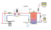
2. A zoned distribution system supplied by an on/off heat pump needs a buffer tank. The tank allows the rate of heat input from the heat pump to be very different from the rate of heat delivery to the distribution system. Without the buffer tank, the heat pump will short cycle, and possibly even trip off on its internal high-head pressure switch when only a small load is present. This tank also serves as a hydraulic separator between the heat input circulator and distribution circulators when piped as shown. This is especially relevant given that there are variable-speed circulators on the load side of the system.
3.There must be a properly sized expansion tank on the load side of the heat pump. In this case, it is mounted near one of the lower connections to the buffer tank. Mounting it on either side of the buffer tank is acceptable.
4. I’ve shown variable-speed circulators that would operate in constant differential pressure mode on the load side of the system. These circulators eliminate the need for differential pressure bypass valves and reduce operating cost. Each manifold circuit connect to low-loss headers that lead back to the buffer tank.
5. Heat pumps should connect to adjacent piping through anti-vibration hose connectors. This helps prevent vibration generated by the compressor from being transmitted to rigid piping.

