The Glitch
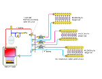
Overview: The system below uses a gas-fired cast-iron boiler to supply three zones of low-temperature floor heating. The installer selects a 1-inch-pipe-sized three-way thermostatic mixing with Cv=3.5 for the mixing device. Each zone is piped in parallel from a common header downstream of the mixing valve.Exercise:Find at least five errors in this layout.
The Fix
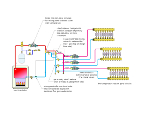
There are several problems with the original schematic. They are corrected in the schematic shown.First, the zone circuits are not equipped with check valves. Without them, reverse flow will develop in circuits that are off. The fix is to either install check valves or use circulators with integral flow checks as shown.
Another serious error is the flow capacity of the three-way thermostatic mixing valve. A valve with a Cv of 3.5 means that a 1 psi pressure drop will occur with a 3.5 gpm flow rate. If we assume a conservative 20-degree temperature drop on the manifold stations, the required design load flow rate would be 12 gpm. At this flow rate, the pressure drop through the thermostatic valve would be almost 12 psi! This is way beyond the capacity of typical 1/25 horsepower zone circulators and, thus, it simply won’t occur.
Instead, flow through the zone circuits will be severely restricted and heat delivery would suffer the same fate. The fix is to use a mixing valve with a higher Cv rating. Select a valve with a Cv approximately equal to the full design load flow rate; this will limit pressure drop through the valve to about 1 psi under these conditions.
Still another problem on the original schematic is a lack of boiler inlet temperature protection. There is no provision for a mixing point to boost boiler inlet temperature. Furthermore, there is nothing to “react” to lower boiler inlet temperature; thus, the boiler is not protected against flue gas condensation.
The fix is to use a motorized three-way valve with a controller that measures boiler inlet temperature and, when necessary, restricts the flow of hot water into the valve so that flue gas condensation does not occur within the boiler. The circulator in the boiler loop is necessary to create the second mixing point that boosts boiler inlet temperature.
Other errors are:
- Circuit purging valves installed backwards.
- Zone circulator inlet too close to header (allow minimum 12 pipe diameters of straight pipe on inlet to any circulator).


