The Glitch
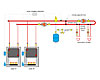
Overview:A multiple boiler system has been configured to supply two loads as shown below.Exercise:There are several piping errors in this proposed design. Can you spot at least five of them?

The Fix
I’ve shown two solutions: The first stays with primary/secondary piping and the other uses a hydraulic separator. Both are viable. The solution using the hydraulic separator allows the supply temperature to each load circuit to be equal.With the primary/secondary system, the supply temperature to the downstream load circuit will be lowered if the upstream secondary circuit is operating.
Here’s a summary of the other corrections:
1. Every boiler in a multiple boiler system should have its own circulator that only operates when that boiler is operating. The original schematic allows flow through all boilers, regardless of which are firing.
2. It may seem simple to be sure the unions are installed between the boiler and the isolating valves, but I’ve seen it otherwise.
3. Always install the supply sensor for the staging controller on the distribution system side of the hydraulic separation point (e.g., downstream of the upper set of closely spaced tees or downstream of the hydraulic separator).
4. Every secondary circuit should be equipped with purging valves to allow efficient filling and flushing.
5. Always locate secondary circulators so they pump into their associated circuit. With this arrangement, the primary loop becomes the pressure reference point and the pressure within the secondary circuit increases when the circulator is on.


