The Glitch
The Glitch
Overview:An installer decides to replace a 30-year-old cast-iron boiler with a modern mod/con unit that has a 5:1 turndown ratio and integral outdoor reset control. He pipes in the new boiler to the existing black iron piping system as shown below. He also installs thermostatic radiator valves (TRV) on the return side of each radiator to provide room-by-room zone control.Exercise:Can you spot some potential problems in the making?

The Fix
The Fix
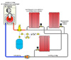
Anytime new hardware is added to an older system, especially a former steam heating system, it’s good practice to install a dirt separator to minimize sludge migration to the new hardware. The old piping should also be flushed out with an appropriate surfactant to remove as much sludge as possible.The mod/con boiler with compact heat exchanger will not like the low flow rates that will occur in the original design when only one thermostatic radiator valve is open (or partially open). This is corrected by hydraulically separating the boiler circuit from the distribution system with a pair of closely spaced tees. It could also be accomplished using a hydraulic separator. The latter would provide air and dirt separation for the system and thus eliminate need to install separate air and dirt separators.
An ECM-based variable speed, pressure-regulated circulator is shown in the distribution system. This circulator will vary its speed as needed to maintain proportional differential pressure across the distribution system as the thermostatic radiator valves open and close. An alternative would be use of a fixed speed circulator with differential pressure bypass valve. However, the pressure-regulated circulator will ultimately have the lowest lifecycle cost through reduced electrical consumption.
The thermostatic radiator valves should be installed on the supply side of the radiators. This helps prevent heat migration from the supply piping into the radiators. The valves shown have angle pattern bodies. This keeps the thermostatic head far enough from the radiator to minimize convective interference that could cause erratic operation of the valve.
Manually operated air vents are shown at the top of each radiator to aid in purging the system.
Finally, a supply temperature sensor that regulates boiler modulation is shown on the supply side of the distribution system (downstream of the closely spaced tees). This allows the boiler to modulate based on the true water supply temperature to the radiators.

