
The Glitch
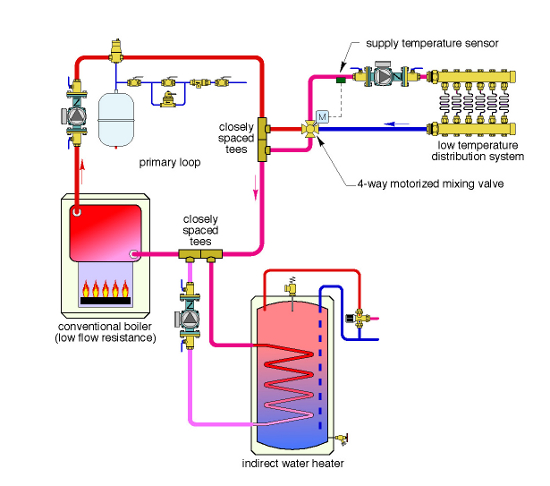
An installer uses a four-way motorized mixing valve to interface between a conventional gas-fired cast-iron boiler and a low-temperature radiant panel system. That system also includes an indirect water heater. The system is installed using primary/secondary piping as shown. The mixing valve is located close to the boiler.
Can you spot at least four details that are either incorrect, missing, inefficient or unnecessary?

The Fix
A four-way motorized mixing valve is specifically design to create two mixing points within itself: one to regulate system supply temperature and the other to boost boiler inlet temperature high enough to prevent sustained flue gas condensation. To accomplish the latter, the controller operating the valve’s motor must sense and react to boiler inlet temperature.
Thus, a boiler inlet temperature sensor is required and is shown in the Fix drawing.
Although a primary/secondary system would work, there are simpler and less costly methods to achieve hydraulic separation between the circulators when the boiler and header piping have low flow resistance. With relatively short and generously sized header piping between the boiler and four-way valve, sufficient flow will be created by the combined effects of buoyancy and momentum exchange within the valve.
Eliminating the primary loop circulator reduces both installation and operating cost. It also eliminates reduced water temperature to the indirect water heater coil if the space-heating subsystem is active, and the water heater is not operated as a priority load.
Did you notice that the primary loop circulator is pumping toward rather than away from the location where the expansion tank connects to the system? That’s definitely incorrect. So is the placement of the secondary circulator serving the indirect water heater. Secondary circulators should always direct water into the secondary circuit. This treats the upstream tee of the closely spaced pair as the point of no pressure change for the secondary circuit. Pressure within the secondary circuit goes up when its circulator is operating.
The supply temperature sensor is located immediately downstream of the four-way mixing valve in the Glitch drawing. Although mixing has begun by the time flow passes this sensor location, it may not be complete and the sensor may not be sensing the final blended temperature supplied to the manifold station. It’s always good practice to install the supply temperature sensor downstream of the distribution circulator to ensure complete mixing has occurred before flow passes the sensor.
Finally, purging valves have been added to the return ends of both load circuits.


