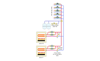
This hydronic system was created to connect two gas-fired, cast-iron boilers to a low-temperature distribution system that supplies 10,000 ft. of 5/8-in. PEX tubing embedded in the floor slab.
The Glitch
The hydronic system shown at the right was created to connect two gas-fired, cast-iron boilers to a low-temperature distribution system that supplies 10,000 ft. of 5/8-in. PEX tubing embedded in the floor slab. A boiler staging controller is used to fire each boiler as needed. The circulator on each boiler is controlled by a standard temperature limit controller on each boiler. Water temperature to the radiant floor circuits is regulated by a variable-speed injection pump.
The installer spends several frustrating hours attempting to get the air out of the system. He finally gets it purged to the point that the distribution circulator is at least moving some water through the floor-heating circuits.
Once the system is fired up, he notices there are times when both boilers are off, yet the injection pump is operating at full speed. Because of this, there is no heat input to the radiant floor manifold and the supply temperature to the floor circuits is noticeably low. After about an hour one boiler finally fires, but it only stays on for a few minutes, and then the above situation repeats.
Can you spot several errors in the schematic that are causing the described problem, or perhaps some other problems? If so, how would you propose correcting these errors?
The Fix
Little details can make big differences. The fact that the boilers stay off for quite a while even though the injection pump is at full speed is caused by the placement of the boiler controller’s supply temperature sensor. It is incorrectly located upstream of the hydraulic separation point; e.g., the closely spaced tees. When the temperature at this location reaches the setting of the boiler staging controller, both boilers are turned off. The boiler circulators, wired through the boiler high limit controller, also are off.
Thus, boiler header piping is full of hot water, but without any circulation. The temperature sensor sits cozily inside its insulated sleeve and “tells” the staging controller that the supply water temperature is right where it should be. Thus, there’s no need to fire the boiler.
Meanwhile, the injection pump is running flat out trying to get some hot water down into the lower temperature piping and out to the floor. The water it pushes up into the boiler header just makes a U-turn and goes back down the “hot” injection riser.
When the boiler supply temperature sensor finally cools off several degrees (which could take an hour or more), the staging controller does just what it should do - it fires one, or maybe even both of the boilers. If the system is under partial load conditions, the water temperature steadily climbs in the boiler header piping, and the situation soon repeats itself.
The Fix drawing shows the boiler control supply sensor relocated to the hot injection riser. This allows the controller to sense and respond to the actual need for hot water injection into the distribution system.
Other details that have been changed include:
1. A properly sized expansion tank. An Extrol 15 is a fine expansion tank in a small residential hydronic system, but it’s much too small for such a large radiant floor distribution system. The expansion tank must be sized for the total volume and temperature excursions of the system.
The make-up water system and expansion tank also have been moved to the boiler return header, where they are close to the inlet side of the boiler circulators.
2. Purge valves have been added to the boiler header piping and the low temperature distribution circuit. The latter is critically important because it’s very difficult to purge across any type of hydraulic separation point in the system. The purge valve in the boiler header, while not critical, will expedite system purging.
3. The air separator has been moved to where the water is at it maximum temperature, and thus its lowest ability to hold gases (air) in solution.
4. The schematic shows at least 12 pipe diameters (e.g., 12D) of straight piping on the inlet side of all circulators and check valves. Less turbulence = quieter operation.
5. The mixed supply temperature sensor has been moved from near the lower set of closely spaced tees to downstream of the distribution circulator. This assures the sensor “feels” the true blended supply water temperature to the manifold, thus allowing stable injection mixing.
Some of you might be thinking that the injection pump should be moved from the “cool” injection riser to the hot injection riser. While this is possible, it is not necessary. The injection pump will function fine as shown. It will even run a bit cooler on the return riser, which might extend its life a bit.


