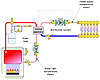
Figure 1.
Many of you reading this column have gained a healthy respect for the ability of a cool concrete slab to suck heat out of warm water passing through embedded tubing. Under the right conditions, a cold slab can pull heat from that water three to four times faster than when the system is operating under design load conditions. It’s amazing to watch this happen. A cool concrete slab is like a black hole for Btus. It gobbles up any heat that dares to get close.
Over the last 25 years, our industry has learned to deal with this in systems where the heat source is a gas-fired or oil-fired boiler. The solution is to install a mixing assembly operated by a controller that measures the boiler’s inlet temperature, as well as the water temperature supplied to the distribution system. This concept, and the placement of the associated temperature sensor, is shown inFigure 1.
The hardware that makes up the mixing assembly can be a three-way or four-way motorized mixing valve, a two-way motorized injection valve or a variable-speed injection pump. All these devices rely on the same thermodynamic principles when it comes to boiler protection.
When the boiler inlet temperature is below some preset minimum (typically around 130º F for a gas-fired boiler), the controller reduces the hot water flow rate from the boiler loop, through the mixing assembly and into the distribution system. The goal is to maintain the boiler’s heat exchanger above the dewpoint of the exhaust gases, thus avoiding sustained flue gas condensation. I’ve watched this control logic in action many times and always with a smile of satisfaction.
Different take
A recent email about an improperly performing system got me thinking about how to apply this boiler protection logic in a different way. Here’s a brief summary of the situation.The problem job involved a very well-insulated house in a very cold climate. The house was heated by a radiant slab in the basement and panel radiators on the first and second floors. The heat source was a 6 KW (20,500 Btu/hr.) electric boiler.
During the day, the basement zone remained off most of the time due to internal heat gains. Under these conditions, the panel radiators worked just fine. However, when the basement thermostat called for heat in early evening, the water temperature available to the panel rads quickly dropped into the range of 70° to 80º. The significant reduction in water temperature prevented the panel rads from maintaining the temperature on the first and second floors much above 60º for several hours. Not surprisingly, such a condition was unacceptable to the occupants.
The cause of the thermal depression was the “appetite” of that cool basement slab after coasting down in temperature for several hours. This transient load in combination with normal load on the panel radiator circuits was more than the 6 KW boiler could handle.
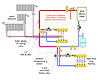
Figure 2.
What to do?
The objective in this situation was not protecting the electric boiler from a low inlet water temperature. Obviously a boiler that operates without combustion doesn’t need protection against sustained flue gas condensation. Instead, this system needed protection against unacceptably low supply water temperatures to the panel radiators while the slab was recovering from a cool condition.We solved the thermal depression problem by using a three-way motorized mixing valve with integrated boiler protection logic applied in a slightly different manner. Instead of installing the boiler temperature sensor on the inlet of the boiler, we placed it on the outlet from the boiler, as seen inFigure 2.
The panel radiators in the system shown in Figure 2 were selected based on a maximum supply water temperature of 140º. The radiant floor circuits required a maximum supply water temperature of 102º. The primary loop through the boiler ensures that the minimum 2-gpm flow rate required by the boiler manufacturer is present whenever either load calls for heat.
Because they require the higher fluid temperature, the panel radiators are the first secondary circuit served along the primary loop. This first load creates a drop in fluid temperature supplied to the second set of closely spaced tees. However, the temperature at the upstream tee is still above that required by the floor-heating circuits. The three-way motorized mixing valve operates with outdoor reset control to provide an appropriate supply temperature to the slab circuits.
Notice that the boiler sensor for the mixing valve is placed ahead of the first set of closely spaced tees. If the controller operating the mixing valve sees this temperature approach, or drop below a set minimum value, it begins closing the hot port of the mixing valve. I describe this control response as a “thermal clutch” that smoothly unloads the primary loop from the thermal appetite of a cool slab.
This ensures that the panel radiators are supplied with a fluid temperature high enough to allow them to meet their portion of the heating load, without having to wait hours for the cool slab to warm back to normal operating conditions. All heat not extracted by the panel radiators goes to the slab. The boiler is operating continuously and at full capacity under such conditions.
Some of you may be thinking that this technique limits how fast a building can heat up follow a setback. This is not true. The boiler would be running continuously and at full capacity during this mode, and its output is what limits how fast the building can heat up. This technique just redirects where, within the system, the heat is being released.
Other opportunities
This technique can be used to protect other loads from the ravenous thermal appetite of a cool slab. A good example is an indirect water heater. Without the type of protection described above, heat stored within the indirect water heater can be quickly stripped away if the circulator for the indirect heater is operating at the same time the slab is warming up. If someone happens to be showering at the same time, it’s going to be exhilarating, but for all the wrong reasons.This technique also can be used on systems where snow-melting is one of the loads supplied by a mod/con boiler. Such boilers don’t require protection against flue gas condensation and, thus, a mixing device is seldom installed between the boiler and the snow-melting manifolds.
However, if other loads such as domestic water heating or space heating are to take priority, a mixing assembly with its boiler sensor monitoring supply water temperature can hold the reins back on that cold slab until ample capacity is available.
Use it where it’s appropriate.


