Figure
1.
If you follow news reports, magazines and Internet blogs about home building, you know that new home construction, although up slightly from this time last year, is still sluggish.
Information published in the home building trade media predicts that the new home construction booms of the past won’t be returning anytime soon. However, many of these sources also point out there has been a significant uptick in residential remodeling. For example, the National Association of Home Builders is forecasting a 10% growth in residential remodeling spending during 2012.
Owners of existing homes haven’t just drawn their curtains waiting for the economy to recover. Many are moving ahead with improvements on their existing homes. Studies by the American Institute of Architects also show that many owners now rank energy conservation as a high priority when investing in home improvements.
Those who install hydronic heating systems are well-positioned to take advantage of this trend. Although any type of heating system could potentially be included in a remodeling project, certain hydronic options offer attractive and often unmatched benefits.
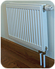
Figure 2.
Nature's gift
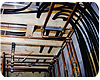
Water is the best stuff on earth for moving thermal energy through buildings. A given volume of water can store almost 3,500 times more heat than the same volume of air. Given standard design guidelines, a 1/2-in. PEX tube carrying heated water can transport heat at the same rate as a 9-in. diameter round duct. The 1/2-in. PEX tube is easily routed through or along framing cavities as seen inFigure 1.I like to describe this advantage by explaining that if you can pull an electrical cable from point A to point B within a building, you can likely pull through some small-diameter flexible PEX, PEX-AL-PEX or PERT tubing to create a homerun hydronic distribution system.
By contrast, a 9-in. round duct would have to be placed between parallel floor joists - assuming no structural bridging, wiring or plumbing is in the way. And while some specialized “I-joist” framing systems allow ducts to pass through large holes in their webbing, it’s highly unlikely to find such framing in retrofit situations.
Routing ducts perpendicular to floor framing usually require exposed soffits or shoving them up into unheated attic space.
Thus, the ability to install hydronic heating using minimally invasive procedures is a huge advantage in retrofit situations. It turns an often impossible situation with forced-air distribution into a noncompromising scenario for hydronics.
Figure
3.
At the end of the line
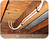
The heat emitters chosen for a hydronics retrofit strategy should be easy to install. In my opinion, panel radiators are one of the least invasive and easiest to install option for retrofit jobs. They’re available in a wide variety of shapes and sizes to fit existing wall spaces and heating loads. They are relatively light and usually can be supported on existing studded walls without additional blocking. Piping is passed up through the two small holes in the floor, as seen inFigures 2and3.The panel radiator shown in Figure 2, as well as each of the other radiators, are equipped with wireless thermostatic radiator valves. These allow room-by-room temperature control, a benefit that few houses without hydronic heat will ever enjoy. It’s all accomplished without electronic thermostats, wires, batteries or transformers. Just set the knob on each radiator valve for the desired comfort level and let them continually adjust the flow as needed.
Another important ingredient in the mix is a pressure-regulated circulator. When set to provide constant differential pressure, it’s an ideal match for a homerun distribution system and panel radiators. Given how pricing on these ECM-based circulators has dropped, you can now buy one for less money than a standard circulator combined with a differential-pressure bypass valve. The latter is required whenever a standard circulator is used with valve-based zoning.
Even if the costs of these options were equal, the ECM-based pressure-regulated circulator can do the job using about 60% less energy than a standard circulator. With good design, a homerun distribution system in a 2,500-sq.-ft. house can operate on 20 to 40 watts of circulator input power, even on a design day.
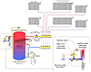
Figure 4.
Simple, stable, efficient
Figure 4shows a schematic that incorporates many of the components and subsystems we’ve been discussing.This system uses a direct-vent, high-mass modulating/condensing heat source with its own internal reset controller. The latter provides “cruise control” of the supply water temperature to the homerun distribution system serving the panel radiators.
Each panel radiator would be sized to the design load of the room it serves, based on a supply temperature of 140º F, and a temperature drop of 30º. This temperature range ensures the heat source always operates within its condensing range. It also reduces flow rates to minimize circulator input power. The lower water temperature limit is determined by the need for domestic hot water. Realistically, the lowest water temperature at the top of the tank, at least when domestic hot water may be required, is about 125º.
A pressure-regulated circulator set in constant differential pressure mode provides “cruise control” for flow through the homerun distribution system. The circulator’s speed automatically adjusts as the wireless radiator valves open, close or modulate.
Besides high thermal efficiency, the high-mass mod/con offers very low head loss. This allows “flow through” design that eliminates the dedicated boiler circulator required in systems using low-mass mod/con boilers. The high thermal mass stabilizes the burner against short cycling, even when the distribution system is extensively zoned.
Domestic water is heated by a brazed-plate heat exchanger located at the side of the heat source. When there’s a draw for domestic hot water, a flow switch, set for 0.5 gpm, turns on a very low power circulator that moves hot water from the top of the storage tank, through the primary side of the stainless-steel heat exchanger, and back to the upper portion of the storage tank.
Cold domestic water is instantly heated as it flows through the other side of this heat exchanger. A thermostatic mixing valve limits the DHW delivery temperature. Combination isolation/flushing valves are installed near the domestic water connections of the heat exchanger to allow for future cleaning.
This system leverages the latest hydronic hardware and design concepts. It’s simple, stable, efficient and adaptable to a wide variety of retrofit situations. Keep this approach in mind when someone suggests that it’s impossible to retrofit an existing home with a high-quality heating system.


