Figure 1
Most heat sources are designed to be installed plumb and level. Solar collectors are the notable exception.
The angle at which a collector is mounted plays a significant role in determining its performance and certainly its aesthetic appeal. This month we will look specifically at factors that influence collector mounting angles in the context of a small solar combisystem, which provides domestic hot water and some space heating to a modest home with low heat loss.
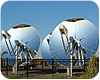
In an ideal world, solar collectors would always face directly at the sun. This is possible using two-axis tracking mechanisms, and it is the norm with concentrating collectors such as those seen in Figure 1.

Figure 2
Thus, concentrating collectors only make sense in areas with many clear days, as well as in applications where high fluid temperatures are required. The cost and potential maintenance associated with the tracking mechanism is substantial compared to a simple fixed mount.
The vast majority of flat-plate and evacuated-tube collectors are mounted in a fixed position. That position can be precisely specified by two angles: tilt and azimuth. Tilt is the angle between the plane of the collector and a horizontal plane. A collector lying flat on a horizontal plane has a tilt of 0 degrees, and a vertical collector has a tilt of 90 degrees. Azimuth is the angle, within a horizontal plane, between a true (polar) north line and the direction the collector is facing. A collector facing directly south has an azimuth angle of 180 degrees. Both angles are shown in Figure 2.

Figure 3
Ideal angles
Software-based perform-ance modeling has been used to establish optimal angles for fixed collectors. These angles depend on the intended load the collectors supply. The two most common are domestic water heating and space heating.Optimal azimuth angle = 180 degrees (e.g., collector faces directly south)
Optimal angle for domestic water heating = local latitude
Optimal angle for space heating = local latitude + 15 degrees
Optimal angle for combisystem = somewhere between latitude and latitude +15
It’s important to remember these angles are based on simulations that assume no shading by surrounding objects such as trees and buildings, and can’t compensate for local conditions - such as heavy snowfall that may not slide off the collectors or consistent morning fog. Every real installation that varies from these assumed ideals, and almost every installation does, requires specific performance modeling.
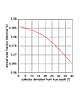
Figure 4
How critical is it?
The only practical way to evaluate the effects of changing collector tilt and azimuth is through computer simulation. Many software packages are available for making such evaluations. Some perform hour-by-hour simulations for an entire year based on the specified system parameters. Others use empirical methods to approximate such simulations using less-intensive number-crunching.For years I’ve used a software package called F-Chart to make such evaluations. F-Chart was originally developed as a “paper and pencil” spreadsheet several years before computers were readily accessible to run mathematically intense simulations. Over the years, it has evolved into a Windows-based software tool that generates instant results for a given set of input parameters (www.fchart.com). I used F-Chart to evaluate the performance of a small combisystem installed in Syracuse, N.Y. It consists of four 4-foot-by-8-foot modern flat-plate collectors configured for drainback freeze protection (e.g., no collector heat exchanger required), and a 250-gallon storage tank. The system serves a small well-insulated house with a 25,000 Btu/hr. design space-heating load at 0 degrees F outdoor temperature, as well as a domestic hot water load of 60 gallons per day, heated from local ground water temperature to 120 degrees F. I varied both collector tilt and azimuth independently to assess performance while keeping all other conditions the same.

Figure 5
That’s only about 2 degrees more than local latitude in Syracuse (43 degrees). The reason is the majority of the solar yield in this system is for domestic water heating rather than space heating. If you’ve ever visited Syracuse in mid-winter, you can surely understand that the solar space-heating potential is pretty limited.
If the space-heating load was dominant against the domestic water-heating load, the optimal collector tilt would increase closer to latitude + 15 degrees.
Figure 3 also shows the decrease in system performance is “mild” for variations in tilt angle, both above and below optimal. For example, at a collector slope of 30 degrees, which in this case is 15 degrees less than optimal, the annual solar fraction is still about 27.5 percent versus optimal at 28.6 percent. That’s a relative loss of only about 4 percent. This also is true for slopes greater than optimal; at 60 degrees collector slope, the annual solar fraction only drops about 4 percent.
A similar result occurs with less-than-optimal azimuth as shown in Figure 4.
If the collector array faced 20 degrees east or west of true south, the estimated drop in annual solar fraction is only about 1 percent. Even at 40 degrees away from south azimuth, the drop in performance is only about 7.3 percent.
I knew someone who went to great lengths to install collectors at EXACTLY the optimum angles - right down to a fraction of a degree. The previous discussion shows this is not necessary. For example, in Syracuse it’s arguably easier to slope collectors at 45 degrees rather than 43 degrees or 48 degrees simply because of ease of construction.

Figure 6
Other factors
There are several considerations other than the pure mathematics of simulated performance. These include:- 1. Snow-sliding potential.
2. Aesthetic considerations.
3. Local shading.
4. Drainage.
The rule of thumb for enabling snow to slide off flat-plate collectors is to slope them at least 40 degrees. It’s also important that nothing impede snow from sliding below the collectors; make sure to include a clear path below them. Snow sliding from evacuated-tube collectors is another matter. In general, it doesn’t happen. If you’re planning to use evacuated-tube collectors in a snowy location, my suggestion is to evaluate them at a tilt of 90 degrees (vertical) and, if possible, slightly below an overhanging eave or other building feature that shelters them from vertical snowfall.
I think it’s important solar collectors don’t detract from the aesthetics of the building on which they’re mounted. This is certainly not the case for the collectors seen in Figure 5. My concern is most people seeing something like this immediately think past energy savings with the reaction “not on my roof.” Better to go with reasonable architectural integration and sacrifice a few percentage points in performance.

Figure 7. (Photo credit: Caleffi North America.)
Another angle worth noting applies to most collectors used in drainback systems. To ensure good drainage, a minimum sideways slope of 1/4-inch per foot is typically recommended both for the collectors and any external piping connecting to them, as shown in Figure 6.
One exception to this is a new patent-pending collector from Caleffi North America, which uses sloping internal headers and a unique “5th port” at the bottom center of the lower header (see Figure 7). This design eliminates the need to side-slope the collectors for drainage and keeps the collector housings aligned with the dominant architectural lines surrounding them.
I hope you have a better feel for the tradeoffs involved in selecting collector angles. A good analytic tool such as F-Chart or other modern solar simulation software, as well as a tool to evaluate location shading potential, are essential if you plan to install solar collectors. Assess the situation analytically, aesthetically and practically, then make your decisions on angles.


