The future of hydronics is low water temperature.
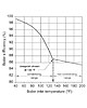
Other than the fact they are all heat sources, what characteristic do mod/con boilers, solar collectors and hydronic heat pumps have in common? Answer: They all perform best when coupled to distribution systems that operate at low supply water temperatures. Here’s the proof: Figure 1 shows how the thermal efficiency of a typical mod/con boiler varies as a function of its inlet water temperature.
Although such boilers can operate at elevated supply water temperatures, even up around 200 degrees F, doing so limits their thermal efficiency to only 1 or 2 percent higher than a conventional boiler operating under the same conditions.
However, when the inlet water temperature drops below the dewpoint temperature of the exhaust gases, usually around 130 degrees F, thermal efficiency increases rapidly. With inlet temperatures under 100 degrees F, most mod/con boilers can deliver efficiencies in the mid- to upper 90s.
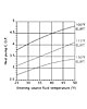
Figure 2 shows how the coefficient of performance (COP) of a water-to-water heat pump is affected by its entering load water temperature (ELWT), the latter being the temperature of the water returning to the heat pump from the distribution system. When supplied with source water at 45 degrees F (a typical mid-winter fluid temperature from an earth loop), and an ELWT of 100 degrees F, the COP of the heat pump represented by this graph is about 4.7, a very respectable number.
However, if the distribution system forces the ELWT up to 115 degrees F, the COP drops to about 3.7. That’s a 21 percent decline in thermal efficiency when operating at a load water temperature only 15 degrees higher.
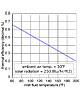
Figure 3 shows how the instantaneous thermal efficiency of a flat-plate solar collector is affected by inlet fluid temperature.
Assuming the ambient air temperature and solar radiation intensity remain constant at the indicated values, which represent a sunny mid-winter day in a northern U.S. climate, the thermal efficiency of the collector drops rapidly with increasing inlet fluid temperature.
Hydronic heat emitters are what determine the system’s operating temperature. The water temperature in any hydronic system only climbs high enough for that system to achieve thermal equilibrium - where the rate of heat dissipation from the heat emitters exactly balances the rate of heat input from the heat source. Once this condition is achieved, there is no need for the water temperature to climb higher.
We all want to maximize the thermal efficiency of the hydronic systems we design. Doing so means moving away from high water temperatures by specifying heat emitters with larger active surfaces, or other details that increase both convective and radiative heat transfer. This allows thermal equilibrium to occur at relatively low water temperatures, both at design load and partial load conditions.
This trend is not new. It’s been taking place on a worldwide basis for more than two decades. Those who work with hydronics in Europe accept this as common practice. North America is perhaps the last place where some new hydronic systems are still designed around higher water temperatures.
Why is this the case? Because most North American systems are designed around price.
Standard fin-tube baseboard is arguably the best example. Originally designed as an alternative to cast-iron radiators, most fin-tube baseboard hasn’t changed much over the last several decades. When fin-tube baseboard first entered the market, fuel was cheap and nearly all boilers operated at water temperatures of 180 degrees F or higher. You could even find heat output ratings for residential fin-tube baseboard at water temperatures as high as 230 degrees F.
The economics are simple. The higher the water temperature, the greater the heat output. The greater the heat output, the shorter the required fin-tube length. The shorter the length, the lower the installed cost.
Please don’t think I’m wagging my finger at the industry saying, “That’s a pretty stupid thing to do.” It made sense when fuel was relatively cheap. Even now, standard fin-tube baseboard would probably regain market share against more contemporary and higher-cost alternatives if fuel prices reverted to where they were in the ’50s and ’60s. That’s not going to happen, so the industry needs to move on.
Emitter evolution
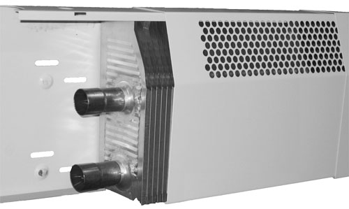
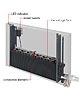
There are definitely some companies that sense opportunity as North America begins to grasp the necessity of low-temperature hydronics. For example, take a look at the fin-tube baseboard product in Figure 4. It’s a product made in the United Kingdom but is now available in the United States.
When both tubes operate in parallel flow, this baseboard has an output of about 287 Btu/hr./ft. when operating with an average water temperature of only 90 degrees F in a room with 65 degrees F air temperature at floor level (based on excluding the 15 percent heating effect factor cited in the IBR ratings). Its output reaches 641 Btu/hr./ft. with an average water temperature of 140 degrees F. Achieving the latter heat output with standard fin-tube baseboard would require an average water temperature of about 208 degrees F.
Although it has twice the water volume of standard fin-tube (two tubes vs. one), the thermal mass is still relatively low compared to other heat-emitter options. This is important for fast thermal response in low-energy buildings with significant internal heat gains.
This product finally acknowledges what is quickly becoming a “progress or perish” situation for traditional fin-tube baseboard. It moves fin-tube baseboard beyond a commodity that trades heat source efficiency for low price into a contender within the arena of future hydronic systems.
Figure 5 shows another contender produced by JAGA North America. By combining a deep, multiple tube fin-tube element with a sturdy enclosure, JAGA has created a product very well-matched to low-water-temperature heat sources. Although its heat output at 100 degrees F average water temperature is about 24 percent of the output at 160-degree F water temperature, the optional rack of “microfans” seen in Figure 5 can boost low temperature heat output by as much as 250 percent. These low-voltage fans only draw about 1.5 watts each at full speed, and are very quiet.
Desirable distribution
Now that we’ve looked at low-temperature heat sources and low-temperature heat emitters, the next logical question is: How do I pipe these together? The answer is a homerun distribution system with a variable-speed distribution circulator.
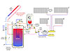
Figure 6 shows an example of such a system combining solar collectors with a mod/con boiler.
The closely spaced tees to the left of the manifold station provide hydraulic separation between the homerun subsystem and the remainder of the system. This isolates the variable-speed distribution circulator from the pressure dynamics created by other circulators in the system.
The three-way motorized mixing valve does two things: First, it acts as a temperature-limiting device against what could be high-temperature water in the storage tank after a sunny spring or fall day. Second, it provides outdoor reset control of the supply water temperature to the heat emitters to stabilize room temperature for optimum comfort.
A setpoint controller continually monitors the temperature at the top of the storage tank. It fires the boiler as necessary to keep the top of the tank warm enough to provide domestic hot water via the internal heat exchanger. The thermal mass of the water in the upper portion of the tank provides buffering to stabilize a highly zoned distribution system and prevent boiler short-cycling. Each panel radiator is sized to supply the design heating load of its room at a water temperature no higher than 120 degrees F.
Radiant panels that can operate at comparably low water temperatures also are contenders. However, when the application is a low-energy-use building, I give the future edge to panels that also have low thermal mass.
In July of 1996, my first Hydronics Workshop column discussed how to use mixing devices to produce low supply temperatures. At the time, achieving low supply water temperatures was more about getting conventional boilers to “play nice” with radiant floor heating systems.
Fast-forward 15 years. Absent a technological breakthrough or a huge drop in fuel prices, I think an ever-increasing percentage of future hydronics systems will operate at water temperatures of 120 degrees F or less under design load conditions. This is especially true if these systems include renewable energy heat sources. Optimizing energy efficiency is now the motivation for low water temperatures. New heat emitters as well as classic low-temperature radiant panels are the enabling technology. I urge everyone in the North American hydronics industry to embrace low-temperature hydronics and tool up to deliver solutions that ensure its implementation.

