Figure 1.
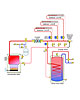
Many suppliers to the North American hydronics market offer both two-way and three-way zone valves. The two-way normally closed, electrically operated zone valve has become the standard for residential hydronic systems. A typical application using such valves is shown inFigure 1.
In this case, a differential-pressure bypass valve is used in combination with a fixed-speed circulator. Another possible configuration eliminates the differential-pressure bypass valve and swaps out the fixed-speed circulator for a variable-speed, pressure-regulated circulator. This alternate means of controlling differential pressure does not change any of the other aspects of the system.
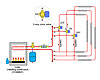
Figure 2.
The Way It Used To Be
Three-way zone valves were developed for situations in which it was necessary to maintain somewhat consistent flow through the heat source as the different zone circuits turn on or off. A typical schematic using three-way zone valves is shown inFigure 2.When a given zone needs heat, the three-way zone valve is energized just like a two-way zone valve. Flow passes from the inlet port “AB” to the “A” port and on through the zone circuit, which contains one or more heat emitters.
When the actuator of the three-way zone valve is turned off, the valve’s internal paddle returns to a position where there is still a flow path from the “AB” port to the “B” port. The circulator remains on, and flow moves through the bypass and back to the boiler.
Even with three-way zone valves, the flow rate through the boiler doesn’t necessarily stay exactly the same, regardless of which zones are on or off. This would only be the case if the flow resistance of the bypass piping in each zone was exactly equal to the flow resistance through the distribution circuit containing the heat emitters. Maintaining constant flow would also require the header piping on both the supply and return sides of the boiler to have very low flow resistance.
You could add a balancing valve to each bypass pipe segment and use it to dial in the required flow resistance that would keep the flow rate through the boiler exactly the same, but usually this is unnecessary. The goal isn’t to keep the flow rate through the boiler exactly the same, the goal is to keep the boiler from developing problems due to insufficient flow. Most boilers, even those with low thermal mass heat exchangers, can handle some variation in flow.
Bob_sm.jpg)
Figure 3.
So why don’t we see more systems piped with three-way zone valves these days? One reason is the complexity and cost relative to systems with two-way zone valves. Another is that constant boiler flow, regardless of the zones operating, can be maintained by installing some form of hydraulic separation between the boiler and the distribution system.
An example using closely spaced tees to provide hydraulic separation is shown inFigure 3.This usually simple method comes with a less expensive installation cost than three-way zone valves.
Since flow is maintained in systems using three-way zone valves, it follows that the electrical operating cost associated with this approach will be higher than in systems where the circulator can adjust its input power based on the zones operating at any time.
We discussed such systems in several past columns. They use a circulator that is either controlled based on differential pressure or differential temperature. In either case, the net result is that circulator speed is reduced as two-way zone valves close, thus electrical power consumption is reduced under partial load conditions.
A circulator operating in a constant differential pressure mode will respond with a speed change within seconds of a zone valve opening or closing. A circulator operating based on differential temperature will likely take a bit longer to respond due to the thermal mass of the system and the rate at which water temperature changes at the sensor locations. The differential-pressure bypass valve can be eliminated with either circulator option. This further reduces the installation cost of the system and, thus, reduces the net effect of the higher cost circulator.
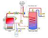
Figure 4.
Life After Three-Way Zoning
So what good are three-way zone valves in these days of variable-speed distribution circulators? Interestingly, as the sale of such valves for zoning purposes decreases, the sale of the same valves for diverting applications is likely to increase.One classic hydronic diverting application is shown inFigure 4.The three-way diverter valve is used to determine if the hot water leaving the boiler is routed to the indirect water heater or the space-heating system. This approach eliminates the need for separate circulators to supply the indirect tank as well as the space-heating system.
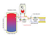
Figure 5.
The decision on which heat source (the solar storage tank or boiler) supplies the load is made by a temperature controller. It could be a simple setpoint controller that energizes the three-way diverter valve to route flow through the boiler if the tank is below some set temperature. It could also be an outdoor reset controller. The latter is likely to produce high solar system performance since it allows the storage tank to remain as the heat source to lower temperatures as outdoor temperatures increase. This improves collector efficiency when the next collection cycle begins.
Bob_sm.jpg)
Figure 6.
When selecting three-way diverter valves, choose a valve that creates a low pressure drop. I suggest selecting valves that will not create more than a 1 psi pressure drop, or 2.3 feet of head loss, at full design flow rate. The latter criteria will be met if you select a valve with a Cv (flow coefficient) approximately equal to the design flow rate.
If you can’t find a standard three-way zone valve with a high enough Cv value, consider a motorized three-way ball valve. Such valves are functionally equivalent to three-way zone valves but less restrictive to flow, thus available with higher Cv ratings.
So, just as hydraulic separation and injection mixing have morphed from their original implementations into state-of-the-art hydronic concepts, three-way “zone” valves are morphing into a new role in system design. As renewable energy heat sources become more prevalent, expect to see more uses for them. Learn to use them as part of your design arsenal.


