Figure 1
Many hydronic heating pros have had the opportunity to use multiple boiler systems in residential and commercial systems. They bring a number of advantages to the system, including:
• Better ability to match heat output to the load.
• Redundancy - if one boiler is down for service, the other(s) can still operate.
• Smaller and lighter boilers compared to a single, large boiler.
• Ability to provide high output to loads like snowmelting and high-capacity water heating while retaining high efficiency under partial load conditions.
These same advantages and more can be achieved using multiple water-to-water ground-source heat pumps connected to an earth loop. The multiple heat pump “plants” can be used to supply heating, cooling or both at the same time, depending on what the load(s) require.
Flow On Demand
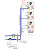
A few years ago, nearly all multiple ground-source heat pump systems maintained earth loop flow throughallthe heat pumps whenever one or more of them was running. Although this kept control simple - just turn on the compressor when the heat pump is needed - it wasted pumping energy. Today there’s a better solution.Figure 1 (page 24) shows a way to configure threeheating-onlyground-source water-to-water heat pumps using a state-of-the-art flow control concept. Flow through the earth-loop side of each heat pump is controlled by a zone valve, or motorized ball valve. Flow only passes through a heat pump when it is on. That flow is created by a variable-speed, pressure-regulated circulator set for constant differential-pressure mode operation.
The circulator is sized to provide the design load flow requirement throughallthe heat pumps (typically about 2.5 gpm/ton of capacity), and the head loss of one of the heat pump branches. The header piping should be kept relatively short and generously sized (e.g., maximum flow velocity of 2 ft./sec). This creates a situation in which almost all head loss occurs across the heat pump’s internal heat exchanger, zone valve and short riser piping - an ideal situation for constant ∆P operation.
Whenever a heat pump shuts off and its zone valve closes, the pressure-regulated circulator “feels” an attempt for differential pressure to rise. It quickly responds by reducing speed until the set differential pressure is reestablished. When speed is decreased, so is input wattage. Depending on load diversity, an ECM-based, pressure-regulated circulator in such an application could save 50 percent or more of the electrical energy required for a constant flow system. Even in modest-size installations, such savings are likely to be into the thousands each year.
The earth loop interfaces with the system through a hydraulic separator, which provides several functions. First, it allows the earth loop flow rate to be different from the flow rate through the source-side of the heat pumps. Earth loop flow could be constant or variable.
Second, the hydraulic separator serves as a high-performance air separator for the earth loop and heat pump source-side piping. I think every earth loop deserves a high-performance air separator. Interestingly, air separators are currently not standard trim in most U.S. residential ground-source heat pumps. In Europe, you would be hard-pressed to find a modern ground-source heat pump system without such an air separator. Must be that American air is more willing to just give up and somehow eject itself from earth loops.
Finally, the hydraulic separator provides efficient dirt separation. Unlike flow-through strainers that create increased pressure drop as they load up with sediment, hydraulic separators simply slow the flow velocity so that dirt particles can drop down out of the flow stream and accumulate in the lower chamber of the separator. A valve at the bottom is periodically opened to flush out the sediment.
In systems where several thousand feet of earth loop tubing is joined together in excavated trenches, it’s inevitable that dirt will get into the system. The hydraulic separator is an ideal way to grab dirt before it goes to work on the earth loop circulator or starts fouling the heat pump evaporators.
Other earth loop details shown in Figure 1 include an expansion tank, fill and purging valves, and an optional fluid feeder. The latter device can automatically add a premixed water/glycol solution to the earth loop based on a drop in pressure. Once the system has been operating, and the dissolved air in the initial charge of earth loop fluid is captured and expelled, the amount of fluid that needs to be added to the system should be very minimal.
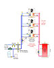
Figure 2
The Load Side
Figure 2 (page 26) adds some load-side components to the heat pump array. As was the case with the earth loop, flow between the heat pumps and buffer tank is handled by a variable-speed, pressure-regulated circulator operating in combination with a zone valve or motorized ball valve on each heat pump.Heat pump operation is based on the temperature requirement of the buffer tank. Typically there is a range of temperature based on a setpoint and a differential centered on that setpoint. For example, if the setpoint was 110 degrees F and the differential was 20 degrees F, the controller will attempt to keep the tank temperature between 100 degrees F and 120 degrees F. It will stage on whatever heat pumps are needed for this task based on PID (proportional-integral-derivative) logic. The setpoint can also vary with outdoor temperature (e.g., outdoor reset control). Lowering the required setpoint under partial load conditions will improve the efficiency of the heat pumps.
The buffer tank provides the same function as it would if connected to an array of multiple boilers. It allows the rate of heat generation to be significantly different than the rate of heat delivery to the load. This allows the distribution system to supply “microloads” without short-cycling the heat pumps. The buffer tank also serves as a convenient hydraulic separator between the heat pump circulator and whatever circulators are used in the distribution system.
Heat, Cool Or Both
Most water-to-water heat pumps come with refrigerant-reversing valves that allow them to produce either heated or chilled water. Figure 3 (page 28) shows how an array of such heat pumps could be configured.This system uses individual circulators with integral check valves to supply the earth-loop side of each heat pump. This is an alternative to the variable-speed circulator and zone valves shown in Figure 1. Given the range of small multiple-speed circulators now on the market, it should be possible to closely match the circulator’s performance to the flow and head loss requirement of each heat pump. Each circulator operates only when its associated heat pump is on.
The load side of the heat pump array uses a diverter valve in combination with a single circulator at each heat pump to direct flow to either the heating or cooling buffer tank.
If the heating load is dominant, the diverter valve would be configured to direct flow to the hot water buffer tank when de-energized, and vice versa.
The system’s control logic would “call” each heat pump into operation in either a heating or cooling mode. The associated circulators and diverting valve would then operate.
This piping arrangement allows some heat pumps to operate in heating mode while others operate in cooling mode. When heat pumps are simultaneously operating in heating and cooling modes, the load on the earth loop is reduced. The heat of rejection from a heat pump operating in cooling mode is dissipated into the piping between the heat pumps and hydraulic separator. Thus, it can be readily absorbed by a heat pump operating in heating mode. The earth loop only needs to handle the “net” low-temperature heat supply or heat dissipation of the system as a whole.
Each load is assessed by the temperature of its associated buffer tank. For example, if a cooling load is active, and the temperature of the chilled water buffer tank is rising rapidly, it’s time for the control system to turn on another heat pump in the cooling mode. Whenever there is a call for heating, cooling or both, the heat pump array is operated to keep each buffer tank within acceptable temperature range. If there is no demand for heating or cooling, there is no point in maintaining the temperature of the associated buffer tank.
Several of the multiple boiler controllers currently on the market can be adapted to multistage heat pump control. Another possibility is a Web-enabled building automation control system.
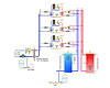
Figure 3
Don't Sweat It!
Keep in mind that all piping and components handling chilled water must be insulated and vapor-sealed to avoid excessive condensation. If you’ve never worked with chilled water systems before, don’t underestimate how important this is. A ceiling can be stained and ruined in a matter of hours from the condensate that will form and drip from a small copper tube installed above it, and carrying water at 40 to 50 degrees F.The buffer tank should be insulated with at least 2 inches of sprayed foam insulation. All piping connections, once pressure-tested, should be sealed with expanding foam and then covered with aluminum foil tape as a vapor barrier.
Modulation Is Coming
One of the most recent developments in heat pump technology is inverter-drive, variable-speed compressors. Like a modulating boiler, a heat pump with such a compressor can reduce its output to about 20 percent of full capacity. These compressors are currently available in some air-to-water heat pumps, which also can be used individually or in a staged/modulating array, to handle hydronic loads.Look for more water-to-water heat pumps to adapt this technology in the very near future. An array of multiple/modulating heat pumps can yield a significantly high system turndown ratio compared to a system with multiple on/off heat pumps. This further improves the system’s load-tracking ability. It will significantly reduce the size of, if not eliminate the need for, a buffer tank.
The big picture continues to be that modern hydronics technology is the “glue” that holds most thermally based renewable energy systems together. It’s where significant performance enhancements are possible when moving from the starting point of a renewable energy heat source and expanding into an overall comfort delivery system. A multiple ground-source (or air-source) heat pump system using variable-speed circulators, hydraulic separation and buffer tanks is a good example.

