
Figure 1
My wife Joyce and I built our house in 1980. It was a long process because we did much of the work ourselves. Anyone who has ever lived in a house as it was constructed can tell you it makes for some challenging experiences. You get used to living with dust, rain tarps, temporary lighting, and the smell of various adhesives and paint. You learn how to wash dishes in the bathroom sink, because it’s the only source of running water at the time.
Joyce envisioned our house as a nest in which to raise children, decorate with lacy curtains and cook great meals. I saw it as my personal laboratory for experiments in home energy systems including superinsulation, air-to-air heat recovery, wood burning, solar and wind energy harvesting, and waste heat recovery.
Being the gracious and supportive wife she is, Joyce indulged me through many years of such experiments. She would call me when there was a “funny noise” coming from the mechanical room, and occasionally reminded me to write a manual on how the system operates in case we ever sold the house. That manual is still on the to-do list.

The Siegenthaler home mid-winter
The Starting Point
Although our primary means of heating the house has changed many times over the last 29 years, the fundamental objectives of energy conservation, gathering “free” energy and using hydronic heat delivery has always been part of the mix.Our original means of heating the home in the snowy, 8,000-degree-day climate of upstate New York included three subsystems:
- Passive solar gain through 360 square feet of south-facing windows;<.li>
- 112 square feet of Revere flat-plate solar collectors; and
- An airtight wood stove.
A schematic of our 1980 vintage solar “combisystem” is shown in Figure 1.
I worked for Revere Solar & Architectural Products at the time. Our house obviously had to have some of the collectors Revere produced. I settled on six 35-inch by 77-inch collectors with specially sloped internal headers. They were installed in a recessed area formed using special roof trusses. I figured this recessed mounting helped shelter the collectors from the prevailing winds, and thus reduced their thermal losses. The collectors face directly south, and are sloped 60 degrees from the horizontal. Figure 2 shows what they look like about mid-winter.
The collectors send heat to a 12-foot tall, 350-gallon storage tank. The height of the tank encouraged temperature stratification (e.g., the hottest water collects at the top, while cool water settles to the bottom). This is always desirable in solar thermal systems. It allows the coolest water to be supplied to the collectors for the best possible thermal efficiency.
It quickly became apparent that a 12-foot tall tank is not the easiest thing to install in a house with eight-foot ceilings. We actually had to build a part of the house around the tank. I figure it’s the next generation’s responsibility to figure out how to remove this tank if ever necessary.
The system was designed as a closed-loop drainback design. I felt this approach held many advantages at the time, and still believe it’s the best approach for solar combisystems that provide space heating and domestic hot water. Two 1/25 horsepower circulators bolted flange-to-flange (series configuration) provide sufficient lift to push water up through the collector array. As soon as they turn off, the water drains back to the tank in about 30 seconds. This system has been through many winter nights with temperatures of minus 20 degrees F or lower, and the drainback operation has never failed me.
The air space at the top of the tank provides a drainback reservoir and serves as the expansion volume for the entire system.
We suspended two 60-foot coils of 1/2-inch copper tubing, piped in parallel, from the access plate at the top of the tank. They heat domestic water whenever hot water is drawn from a fixture. Over the years I’ve been very pleased with the performance of this homemade heat exchanger. Although it’s possible to service this heat exchanger, I’ve never had to pull the plate off the top of the tank, and don’t plan to as long as these suspended coils keep working.
When the tank was warm, space heating was provided by circulating water through copper tubing embedded in a thin masonry layer installed over the standard subfloor. At the time, we could buy 100 foot coils of 3/8-inch type L copper water tube directly from Revere, which we used to fashion the floor circuits. Everything was soldered together, and still is. We installed a manually adjusted mixing valve in case the water in the tank was too warm to go directly to the floor circuits.
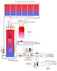
Figure 3
Living With The Results
By the middle of the first winter, Joyce and I were waking to 55-degree inside air temperatures. If the day looked cloudy, we kindled the wood stove and waited a couple hours for things to warm up. On clear winter days, we would just wait for the sun to work its magic. By mid-afternoon, the inside temperature would climb to around 85 degrees F. We would start our day wearing multiple sweaters, and by afternoon be down to T-shirts.Back then, when asked about the performance of our solar house, I was inclined to say it maintained an “average” interior temperature of 70 degrees F on a clear and cold winter day. A mathematically true statement, but certainly a bit misleading. Today, I would describe the original experience as a ride on a temperature rollercoaster that few occupants other than solar diehards would tolerate.
By the late 1980s, Joyce and I were ready to add an automatic heat source to the system. At that time, our local utility was offering very enticing rebates to seed the market for heat pump systems. We took advantage of this program and, in 1987, I installed a small (18,000 Btu/hr. rated) water-to-water ground source heat pump.
Because the heat pump involved flow of both warm and cool water, I decided it was also a good opportunity for further experimentation. The system was modified to the status shown in Figure 3.
The solar portion of the system remained essentially unchanged. The water-to-water heat pump was piped to the existing solar storage tank connection points (we didn’t have the option of punching new holes in the tank for more connections). Heated water leaving the heat pump went to the top of the tank, while cool water was drawn from the bottom. This helped preserve temperature stratification within the tank. I used a simple capillary-tube setpoint controller to turn the heat pump on and off as necessary to maintain the temperature at the top of the tank around 115 degrees F.
Heat Recovery Ventilation
Water leaving the heat pump’s evaporator would drop down to about 35 degrees F by late winter. That’s cold enough to suck heat out of quite a few things, including air streams on their way out of the house. To recover some of this heat, I added a small (12,000 Btu/hr. rated) air handler with a drip pan, and shunted some of this cool water leaving the heat pump through its coil (see Figure 3).Air entering this air handler came from two sources: the clothes dryer and a high wall exhaust in the bathroom. Both exhaust streams contained sensible and latent heat. When run past the air-handler coil, they transferred some of this heat to the chilled water headed back to the earth loop. The heat exchange was such that I never had to add antifreeze to the earth loop. We installed a polypropylene grid filter upstream of the air handler to keep lint from the dryer exhaust from collecting on the coil. It did a great job and got cleaned weekly. The heat recovery ventilation system was set to run whenever the heat pump operated, or when a humidistat in the house called for ventilation.

Figure 4
Time To Chill
Occasionally it gets uncomfortably warm and humid in upstate New York. Were we live, this only happens about 5-10 days each summer. Knowing that the heat pump could produce chilled water, I just couldn’t resist expanding the system for chilled water cooling. This time we added a small ceiling-mounted, cabinet-style air handler as seen in Figure 4.This set up did a great job of keeping us comfortable on those sticky days. With 38-degree water passing through a three-row coil, the air handler was phenomenal at reducing humidity. With a cooling capacity of about 12,000 Btu/hr., the unit ran almost continually on hot days. That’s good from the standpoint of minimal compressor cycling, and lots of air recirculation through the coil for moisture removal.
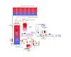
Figure 5
What's Next?
About nine years ago, we finally got around to insulating and finishing our garage. Snow and ice get dragged into this garage almost every time the cars come back from a winter outing. Being tired of getting into ice-cold cars covered with layers of dirty snow, we decided to partially heat the garage. I’m sure this would have been out of the question based on my 1980 philosophy of energy conservation, but age, ice choppers and ankle-deep slush as you step out of the car tend to “mellow” one’s convictions over time.We jack-hammered out the old slab, installed floor heating circuits and poured a new slab - this time with the proper drainage. The only remaining issue was where the additional heat for the garage was going to come from? The heat pump had just enough capacity to heat the house.
At the time, No. 2 fuel oil cost about $1/gallon. At that price, the heat produced by a standard oil-fired boiler would cost us less than that provided by the ground source heat pump. This tipped the scales in favor of installing an oil-fired cast-iron boiler to heat the garage, the house and provide supplemental heat for DHW. The heat pump was moved to accommodate the boiler, but it was reconnected to the original chilled water air handler, and still works fine for summer cooling.
The ventilation air handler eventually succumbed to corrosion, and was not designed such that the drip pan could be replaced. Without the heat pump operating during winter, the potential for heat recovery was greatly reduced, so I decided to remove this part of the system. The ventilation air and dryer exhaust now go straight outside. Watching steam from the dryer exhaust dissipate into cold winter air probably would have driven me crazy 30 years ago. Now I view it as an acceptable compromise, and hope the “green police” will go easy on me once they spot it.
Figure 5 shows how our heating/cooling system was last modified about nine years ago. At the time, injection mixing and primary/secondary piping were the cutting-edge technologies, so naturally they had to be worked into the mix. You’ll notice there’s an extra set of closely spaced tees on the primary loop waiting for some future experiments.
This brings us to the present. After 29 years, the solar portion of our system is still ticking. I’m sure the collector efficiency has degraded a bit over this time, but the tank is still toasty at the end of a sunny day. Even the original Independent Energy C-100 solar controller is still functioning, despite a power surge that cooked its innards, and forced me to grab a soldering iron for a transformer transplant. The original radiant floor is still working well, and so are all but one of the original circulators. I wish I could say the same about our original refrigerator, washing machine, dryer, well pump and range. Few appliances can ever hope to outlast a quality hydronic heating system.
Would I do things differently given the chance to start from scratch? Absolutely! Was the evolution of this system a great learning experience that improves what I do on other designs? Without a doubt. In a professional sense, nothing beats “quality time” watching, feeling and listening to a system operate. This experience is guaranteed to teach you things you won’t find in any textbook or installation manual. The lessons I learned from my own system proved invaluable for future design work, and even some occasional writing assignments.
Every heating system designer should have a system they can modify over time to test new ideas, and verify how they work before incorporating them into other systems. I was especially fortunate to have my experimental platform right at home. I was also blessed to have a wife who supported me through the evolution of our system. Now if I can just get that system operating manual written…

