
Figure 1
The last time I counted, there were at least 18 manufacturers supplying modulating/condensing boilers for the North American hydronics market. Most of these boilers have sophisticated controls that monitor a variety of temperature and pressure sensors to ensure the boiler is operating within its intended performance envelope.
Many of these controls assume the boiler is installed in a “template” system for supplying space heating and domestic hot water. As long as the boiler is installed in a template application, the functions provided by the boiler controller usually make sense. However, when the boiler ends up in an alternative system configuration these functions can, at times, get in the way.
Here’s an example: Imagine you’re designing the control system for a boiler and think it’s important to protect the boiler from freezing in case the building’s thermostat fails to call for heat, or somebody leaves the door between the mechanical room and the outdoors open. This is certainly a possibility. So, you code instructions into the controller’s firmware that watches for a condition where there’s no call for heat, and the temperature sensor inside the boiler drops to 40 degrees F. If this combination occurs, your instruction set tells the boiler to fire at a low rate and run the circulator to keep the boiler from freezing. Seems reasonable, doesn’t it?
Now, one of these boilers gets selected for a snowmelting application, and it ends up installed in an unheated garage. Since the system is filled with glycol, you know it’s protected from freezing. You know this, but the firmware in the boiler controller doesn’t. So as the temperature in the garage drops off during winter, the boiler controller detects the combination of no call for heat and the boiler temperature at 40 degrees F. At that point it turns on the boiler and a circulator to prevent what it thinks is a potential freezing condition. The result is that fuel is consumed when there is no need for snowmelting.
There may be a way to subvert this mode by entering the programming mode of the boiler and turning this feature off, or by installing additional switches and controls that simply interfere with what the boiler is attempting to do in protecting itself. The issue here is that some of the conditions assumed for template system don’t always make sense for other applications, and can even create unintentional operating modes.
Another situation our industry continues to deal with is that most mod/con boilers do not modulate low enough to prevent short cycling in microload situations. Imagine a very well-insulated house with a design heating load of 30,000 Btu/hr. On a design day, this house only requires 60 percent of the rated output of the smallest (50,000 Btu/hr.) mod/con boilers currently available in North America. These boilers usually modulate down to 20 percent of their rated capacity, and thus the smallest currently available mod/cons operate at a minimum continuous heat output rate of about 10,000 Btu/hr.
But what happens when the only active load is a short floor heating circuit or a single low-mass panel radiator? Ten thousand Btu/hr. of heat generation, combined with perhaps 1,500 Btu/hr. of heat release, and 2 or 3 gallons of water in between results in thousands of “burner burps” over the course of a heating season. Such cycling increases wear on the boiler components, especially the ignition system.
Granted, houses with design loads of 30,000 Btu/hr. may be the exception right now. But if present trends continue, all energy costs are certain to undergo significant increases in the very near future. Where will that drive insulation requirements in energy codes? How will it affect decisions made by increasingly energy-conscious consumers looking for housing? Does anybody remember the term “super-insulation” from the early ’80s? It’s sure to make a comeback as Americans face monthly utility bills that rival their mortgage payments. The hydronics industry needs a solution that harmonizes with this trend toward smaller loads, while still providing superior comfort, room-by-room control and reliability.
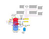
Figure 2
Thermal Mass To The Rescue
Rather than creating a boiler with enough “smarts” to handle every possible situation, why not use the mitigating effect of thermal mass? Here’s the idea: Create a condensing-capable burner/heat exchanger assembly, but operate that burner in an on/off manner. Couple this with a well-insulated buffer tank - think Thermos bottle - with sufficient water volume to absorb any surplus heat output through a modest increase in temperature. Once the tank’s water has risen a few degrees above the required water supply temperature, turn off the burner, and allow the tank temperature to coast down as heat is extracted by whatever load happens to be active.If that load happens to be a single small panel radiator, the coast down might take an hour or more. So be it. As long as the tank’s thermal mass can supply the load, there’s no need to fire the burner. A conceptual schematic is shown in Figure 1.
Burner operation is controlled by a simple outdoor reset controller that continually calculates a target supply water temperature for space heating based on outdoor temperature. The burner would operate at full-rated output until the tank’s water reached this target temperature, plus some “half-differential” of perhaps 8 to 10 degrees F. At this point, the burner would turn off and the tank would supply heated water to the load as required. When the tank’s temperature dropped to the target temperature minus the same half-differential, the burner would restart. The strategy “exercises” the thermal mass and allows the burner to remain on for several minutes each time it fires. It’s unlikely the modest variation in supply temperature would even be noticed by building occupants.
Unlike some present generation mod/con boilers with compact heat exchangers, the buffer tank with integral burner would create very little flow restriction, and thus would dissipate virtually none of the circulator’s head energy. A set of short, generously sized headers would connect the tank to load circuits and provide hydraulic separation between them. This configuration eliminates the need for primary/secondary pumping (e.g., closely spaced tees or a hydraulic separator). It also allows the distribution circulator(s) to be sized for the head loss of the distribution system alone, without the added head loss of the heat source. This reduces circulator power requirements and lowers the electrical operating cost of the system.
A coalescing media for capturing microbubbles is shown within the tank, just upstream of the outlet to the space heating load. This is only a conceptual drawing, but considering that water in this location is hot and moving very slowly, the coalescing media should perform similar to how it does within the shell of a separate component. If so, this arrangement eliminates the need for an external central air separator. One less device to install in the field, and one small step toward a more integrated “heating appliance” vs. simply a heat source.
As an option, an internal heat exchanger could be mounted near the top of the tank to provide domestic water heating - sort of a tankless coil on steroids approach (see Figure 2). This configuration would require the temperature at the top of the tank to be maintained sufficiently high to supply domestic hot water at any time, and hence would limit the lower range of the outdoor reset control operation. The added thermal mass would allow for small draws of domestic hot water without need of firing the burner - an advantage, in my opinion, over instantaneous water heaters. With a generously sized heat exchanger, the added thermal mass also lets the appliance temporarily sustain hot water delivery rates in excess of the heating capacity of the burner.
The concept can be further expanded by adding another heat exchanger to accept heat input from a solar collector array or other intermittent heat source (see Figure 3). Keeping this heat exchanger low in the tank allows it to operate at the lowest possible temperature and thus increases solar collection efficiency. It also allows the hottest water to remain stratified at the top of the tank where loads are supplied.
Note that a three-way mixing valve has been added to the distribution system in Figure 3. This is highly recommended to protect low-temperature heat emitters from potentially high water temperatures due to sustained solar input to the tank.

Figure 3
Back To The Future
In some respects, this concept is a throwback to condensing boiler designs of the past. During the 1980s, there were at least two residential product offerings that merged a condensing-capable burner/heat exchanger assembly with an insulated storage tank. Perhaps these products didn’t prevail because new designs came along with the intent of displacing thermal mass through modulation. Perhaps the materials used in these early products did not stand the effects of flue gas condensation as well as current generation products. Maybe these products had inadequate insulation to minimize heat loss during standby mode.Whatever the reasons, there are now compelling reasons for our industry to revisit the combination of a very well-insulated thermal mass tank merged to a condensing-capable burner and simplified controls.
This combination provides a backbone to support numerous contemporary subsystems like variable-speed distribution circulators, homerun distribution and solar augmentation. Together, these subsystems provide high thermal and hydraulic efficiency, excellent microload compatibility and a simple hardware configuration that’s easy to repeat from one house to the next. This is all accomplished without gobs of hardware or complicated controls.
Given these benefits, will “mass/con” soon become part of our trade vocabulary?

