
Figure 1.
The availability of heat from some of these sources is sporadic. Obviously, solar input only occurs when the sun is out, and heat from a wood-fired or pellet-fired device is only available when the fire is burning. Heat input from a geothermal heat pump might only be economically desirable during periods of low off-peak utility rates. To further complicate matters, the water temperature supplied from these heat sources can vary widely.
So how does one set up a system to accommodate two or three of these heat sources? One approach would be to install an elaborate collection of controls. Together, these devices could decide which heat source has priority depending on the current and anticipated loads, the cost of operating the device, the temperature and heat output rate of each device. The logic would also have to address the avoidance of short-cycling the various heat sources.
Once the logic is determined, attention would turn to piping all these devices together. This piping would probably include devices such as mixing valves, primary/secondary piping, heat exchangers and multiple storage tanks - the works. This approach gets complicated and expensive at the same time.
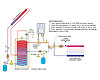
Figure 2.
A New Hub
During my visit to the Mostra Convegno Expocomfort in Milan, Italy, this past March, it was evident that several European manufacturers have recognized the need to combine multiple heat sources into a single system. This is especially relevant given the growing use of renewable energy in Europe. Their approach, depicted in Figure 1, uses a single large storage tank as the “thermal accumulator” in the system.Each heat source “deposits” heat to the thermal accumulator whenever it operates. The thermal mass of the water accepts this heat without abrupt changes in temperature, and thus helps protect the heat source(s) from short-cycling.
Thermal accumulators service both space heating and domestic water heat loads. A common configuration uses an internal heat exchanger near the bottom of the tank to accept input from an array of solar collectors. Placing the coil there allows the collector circuit to operate at the lowest possible temperature and the highest possible efficiency.
Another coil, located near the top of the tank, is used to add heat from a boiler when necessary. This allows the coil to boost the temperature of the water at the top of the tank without disturbing the temperature stratification within the tank (e.g., keeping the warmest water at the top and coolest water at the bottom). The heat source connected to the upper coil would operate to maintain a suitable delivery temperature for domestic hot water. This concept is shown with a bit more detail in Figure 2.
The majority of the water in the thermal accumulator depicted in Figure 2 is potable water. An anti-scald tempering valve intercedes between this water and the plumbing fixtures. This is an absolutely critical detail given the potential for high tank temperatures during sunny warm weather.
Other thermal accumulators are designed to hold space heating water in the main tank shell. Potable water is heated within a small internal tank mounted in the upper portion of the main tank. The inner tank is completely surrounded by hot water and, thus, has ample area to rapidly transfer heat to potable water it contains (see Figure 3). Operating modes are the same as shown in Figure 2.
Still another variation is an unpressurized polypropylene tank that simply contains stationary water as the mediating thermal mass. All subsystems add or remove heat from this water via a coil or internal tank. An example of such a tank is shown in Figure 4.
The manufacturer of this product emphasizes that the stationary water within the tank provides superior temperature stratification (warmest water at the top, coolest water at the bottom).
Another cited advantage of this design is that minimal volumes of domestic water are stored within the DHW coil. This reduces the potential for legionella growth. Keep in mind that a small volume of DHW doesn’t imply low delivery capability. There’s always plenty of thermal energy parked in the tank’s stationary hot water ready to instantly move through the coil wall to keep the DHW flowing.
The heat storage ability of this thermal accumulator can be enhanced by adding up to 44 pounds of paraffin wax, which melts upon heating to 55 degrees C (131 degrees F) and floats on top of the water. As the tank cools, the wax goes through a phase change from liquid to solid and gives up significant heat in the process. The wax layer also reduces evaporation from the tank.
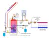
Figure 3.
Superinsulation
At trade shows like Mostra or ISH, it’s quickly evident that European manufacturers take their insulation seriously. Seldom will you see uninsulated pipe, even in situations where the pipe passes through heated space. Ditto for tank insulation. Most thermal accumulator tanks have at least 3 inches of foam insulation surrounding the entire water vessel. Some use rigid urethane foam. Others use a flexible foam wrap that’s installed on site. This allows the tank shell to fit through narrower doorways. Once set in place, the insulation wraps around the tank, and closes up with a heavy-duty zipper.One manufacturer lists the thermal loss of its thermal accumulator at 0.1 degree Kelvin/hr. This converts to 0.18 degree F per hour. It states that a thermal accumulator initially heated to 95 degrees C (203 degrees F), remaining in standby mode, will still be at 70 degrees C (158 degrees F) eight days later. Compare this to some North American tanks that proudly promote losses of only 0.5 to 1 degree F per hour.
The way I see it, if you’re going to build a high-quality device to accept and deliver heat precisely when and were it’s needed, why not built it like a big Thermos bottle? You wouldn’t be pleased with an electrical battery that self-discharges in a few hours, why accept such performance from a “thermal battery?”

Figure 4.
Tanks Needed
Thermal accumulators provide a lot of synergistic benefits, including:In past columns I’ve stressed the need for more sophisticated thermal storage tanks in the North American hydronics industry. Tanks with multiple, generously sized heat exchangers, superinsulated shells and plenty of piping connections. To date, the only tanks that I’m aware of fitting this description come from across the pond.
With interest in solar heating rapidly increasing in North America, perhaps now is the time for North American manufacturers to step forward with their own thermal accumulator products. I can’t help but think there’s a growing audience ready to put them to good use.
