John Siegenthaler: Symbolism
Tips on creating and using CAD drawings for hydronic design.
If you've followed the "Hydronics Workshop" column for some time, you've probably grown accustomed to schematic drawings. Be it piping or electrical systems, schematic drawings are the "language" through which the intricacies of modern hydronic systems are communicated.
At times, most of us have read a text-only description of how a sophisticated hydronic system is piped or wired. From that description, we've tried to picture how the hardware is arranged.
Unfortunately, terms like primary/secondary, pumping away and thermal trap can conjure up different images for different people. This makes it difficult to get an accurate picture of how the system is, or will be assembled. Without this picture, it's very difficult to give definitive advice on installation or troubleshooting. The old adage of a picture being worth a thousand words comes to mind as we struggle to see what someone else is trying to describe in words.
The picture of choice in these situations is a schematic drawing. The intent of a schematic is to show the relative positions and interconnections of the various components in a system. These relationships are established as the system is designed, and must be precisely communicated to those installing it.
Although not intended to show the exact three-dimensional location of all components, a well-drawn schematic does help the installer build a three-dimensional assembly from a two-dimensional drawing.
Several of you have contacted me about how to draw piping and wiring schematics. Some have been looking for recommendations on drawing software, others have inquired about where they could obtain predrawn piping and electrical symbol libraries for use with software they already own. This month we'll look at the basics of making piping schematics using computer-aided drawing (CAD) software.
Have It Your Way
Although piping component symbol libraries do exist and are shipped with many CAD programs, such symbols may not be what you, or those interpreting your drawings, are familiar with.
Unfortunately there is no universally accepted symbol palette for hydronic piping symbols used across the United States, much less the rest of the world. Even if there were, such a palette would have to be continually updated to reflect new products (i.e. a wall-hung condensing boiler vs. a floor-mounted cast-iron boiler, or radiant manifolds with and without integral flow meters). Therefore, my recommendation has always been to create the schematic symbols using the same CAD program you will use to arrange them into schematics.
Some who follow this advice will choose to keep their component symbols very simple. This may be the result of limitations of the computer software and/or their own level of experience using it. Others will take the time to create detailed component symbols replete with colors and shapes that easily identify them as a particular product. Either approach is acceptable. The key is to stay consistent.
I prefer to create somewhat generic symbols. One reason is not to point to a specific product as being the only possible solution. Another is to stress that the relationship between the selected hardware is almost always more important than the exact hardware shown.
Figure 1 shows the piping symbol legend I developed for the second edition of my text "Modern Hydronic Heating." I'm presenting it in hopes that many of you can adapt these symbols as your standard.
If you decide to recreate these symbols, be sure to maintain the relative size of the symbols. Obviously most boilers are larger than most pressure gauges. The proportions of the symbols reflect this. These proportions also let the schematic bear some resemblance to the system that will be built from it.
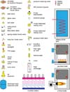
Figure 1
CAD Options
If you are looking to draw high-quality piping and electrical schematics, as well as scaled radiant tubing layouts, you need a "true" CAD software package. Although there are many to choose from, I highly recommend two.
If you work on a Windows-based operating system, take a look at VISIO Professional 2002 from Microsoft Corp. (www.microsoft.com/office/visio/). As of this writing, Microsoft sells the professional version of VISIO through its Web site for $499. However, a bit of Internet shopping will find it for around $350, or even less if you happen to be a student or instructor.
Although VISIO comes with many symbols, they may not be exactly what you are looking for, especially if you intend to use symbols that resemble specific products. Like any CAD program, VISIO allows you to create your own symbols, which in VISIO vernacular are called "stencils." You could make these stencils resemble the symbols shown in Figure 1 or, with a little more time, make them look almost exactly like the components you sell or install.
Many of the hydronic professionals who have used it rave about the short learning curve and powerful features of VISIO, especially in comparison to other "established" high-end CAD software. The latter can cost several times more, and takes months rather than days to learn to the point of reasonable productivity.
I've also watched some remarkable demonstrations of "smart" VISIO stencils. In one, a stencil representing a serpentine pattern for a radiant floor circuit was stretched while retaining the "connectivity" between arcs and straight lines. The displayed length of the circuit changed as the circuit was stretched like a rubber band into the proper place on the floor plan.
VISIO was generating the circuit image as well as simultaneously calculating the circuit's length. The person who taught VISIO this highly useful skill is Piotr Zelasko of Park Supply in Chicago. If you ever have a chance to watch him wield VISIO as a specialized hydronic design assistant, you, too, will be amazed.
For The Other 5 Percent Of Us
I happen to prefer an Apple Macintosh as my digital desktop. I've used Macs for years, and try not to get too fanatical about them -- other than telling people they can have my Mac when they pry it from my cold, dead fingers!
For 10 years, I used software called Claris CAD. This package, which first appeared in 1991, was a great product in its time. Unfortunately, Claris eventually decided they were better at database software, and failed to upgrade their aging CAD product. This meant sure extinction as new operating systems and hardware eventually would no longer support older software.
While searching for a replacement I came across a product called PowerCADD 2000, which is a phenomenally capable yet easy-to-use package. All the drawings you've seen in my PM columns over the last few months were generated using it. If interested, you can check it out and download a demo at Engineered Software (www.engsw.com).
I don't recommend pixel-based "painting" software for generating piping or electrical schematics. Although it is possible to generate simple shapes and fill them with wild colors, this type of software lacks the "snapping," scaling and other geometry manipulation tools necessary to produce clean, accurate and sometimes complex schematics.
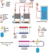
Figure 2
Draw Once/Use Many
Regardless of the CAD software you use, the name of the game in drawing schematics is to reuse the same symbols over and over.
The concept of "copy and paste" is the key to being productive. With a good symbol palette established, you will seldom, if ever, need to redraw a component symbol from scratch. Every copy of every symbol will show the level of detail you established when creating it.
Considering that you'll eventually use thousands of copies of each symbol, it makes sense to draw each of them accurately when creating the original palette. If you need to show a symbol at a size different from that in the palette, use the CAD software's scale command to shrink or enlarge it while maintaining the exact proportions.
After creating your symbol palette, set up a "stationary" drawing for piping schematics. Select the drawing size, line widths and layer system you prefer, then copy and paste your symbol palette into the stationary drawing. Create the schematic by duplicating symbols from the palette, and pasting/dragging them into position on the piping lines.
If the component symbols were created with a fill color, they can be placed "on top of" the lines representing piping. In most CAD software, this is done by placing the symbols on a different layer than the lines representing the piping.
This approach allows the symbol to mask over the line beneath it without breaking or erasing part of that line. This is a real time saver when symbols need to be moved around as the schematic takes form.
Use the "save as" command the first time you save the stationary file from which you started the drawing, and be sure to change the file name from that used for the stationary file. This allows the stationary file to remain unaltered and ready to start a new drawing.
Get in the habit of saving the drawing file to disk every few minutes as you work on it. Some CAD software can be set up to do this automatically. There are few things more frustrating than watching the last hour of your creative efforts instantly evaporate as some wayward byte zigs when it should have zagged.
I also highly recommend getting an uninterruptable power supply for your computer system. You never know when the electric utility may pull the switch, or when Mother Nature might pull it.
The more schematics you draw, the faster you'll draw them. You'll quickly discover that entire piping assemblies rather than just component symbols can be copied and pasted.
In many cases, a new piping schematic will be drawn mostly by modifying an existing drawing rather than starting from the stationary drawing file. Figure 2 shows some examples of possible piping subassemblies that could be used in hydronic piping schematics.
Getting Over The Hump
I've yet to find a CAD package where you press a couple keys and it generates a complete and properly designed hydronic heating system. Instead, CAD software is a powerful tool to be directed by a trained mind. You might compare it to a power saw vs. a handsaw in terms of potential productivity, but turning that potential into reality requires a commitment on your part.
If you're used to manual drawing and are trying to switch over to CAD, you'll surely be tempted to go back to the drawing board when first learning the software. I spent 13 years behind a drawing board and can tell you it's a hard habit to break, especially given some of the nuances of dealing with computers in general.
I suggest learning your new CAD software by forcing yourself to produce all the drawings for a pending project. This makes you find and use the commands and techniques most relevant to what you need, instead of simply reading the user manual from front to back.
It will be slow going at first, and you will make many mistakes, but trust me that if you persist, you will make it "over the hump." You'll soon find your brain focusing on what you are drawing rather than how you are drawing it. Your fingers will subconsciously find the necessary keys and pull-down menus. You won't need to refer to the help system or user manual every few minutes.
At that point, you'll never look back at the drawing board as a productive drawing tool. Your attitude will quickly change to: Why didn't I do this a couple of years ago? From this point you'll delve deeper into the advanced drawing tools available in all modern CAD software. You're then well on the way to becoming a "power user."
CAD will help your company look and be more professional. Besides producing accurate drawings that prevent misunderstandings and installation errors in the field, you're creating a tremendous marketing tool. Showing prospective clients the quality computer-generated schematics you've produced for previous projects is surely more impressive than scribbling out the schematic for a $20,000 heating system on the back of a business card.
Show Me The Money
Please don't get so excited about CAD that you eagerly produce and hand out fully detailed drawings with every quotation. The time required to generate drawings must be factored into the cost of every job. Never offer clients the drawing(s) for a proposed system until you have a signed commitment on the project. I don't need to tell you what happens if you do.
Once you've got that commitment, the time spent producing the drawings is not time "lost," or time "spent," it's time invested. That investment pays dividends including higher productivity, fewer mistakes in the field, permanent documentation for long-term troubleshooting, and impressive materials that help market you as a professional.
I would like to see some of the schematic drawings that PM readers have used or are currently producing for upcoming hydronic installations. If you have some CAD-generated schematics that you're particularly proud off, e-mail a copy as a .PDF, .EPS or .JPEG. (If you don't know what those letters stand for, go back and read your user manual.)
I'll pick out some good examples and show them in a future column. In the meantime, keep those mouse buttons and keyboards warm.
Hydronics Know-How
Now available is an updated CD-ROM version of John Siegenthaler's "Hydronics Toolbox," titled "Hydronics Know-How." It features a new forward and update to Hydronics 101 seen in the first edition. Order a complete collection of 100+ of John's columns and features in PM and PME ($75+ shipping) by contacting Lisa Frost at 248/244-1290 or Frostl@bnp.com.
John Siegenthaler At ISH NA 2003
John Siegenthaler is a scheduled speaker at this year's ISH North America Tradeshow held Oct. 1-3 in Las Vegas, Nev. He will present two seminars: "Cures for Short Cycling in Hydronic Heating Systems" on Wednesday, Oct. 1 at 9 a.m.; and "Radiant Basics/Precision," an all-day session sponsored by the RPA on Friday, Oct. 3 beginning at 9 a.m. To register for the show, visit www.ish-na.com.
Looking for a reprint of this article?
From high-res PDFs to custom plaques, order your copy today!


