I’m writing this column in mid-November. In upstate New York, as in other parts of the county, the annual match-up between deer and hunter is in full swing. Lot’s of folks can’t wait to get up in their tree stands by 5 a.m. and sit patiently, sometimes for hours, until the perfect shot is at hand. Their goal is to hit an imaginary bull’s eye on that deer, so that a second shot won’t be necessary, and their freezer will soon be filled with venison. The skill, dedication, and hardware necessary to make that perfect shot happen is truly impressive.
Hydronic heating pros get to shoot at specialized targets all year round. The center of their bull’s eye might be a specific temperature or flow rate within each system they design. They use skill, dedication and the right tools to make their shot (the installed heating system) hit as close as possible to the bull’s eye (the intended operating conditions). Let’s review the “classic” procedure for making each of those shots count the first time.
From Load To Circulator
Determining the pipe size and circulator requirement for a distribution circuit is as fundamental to hydronics design as selecting a wire size is in designing electrical circuits. Every hydronic heating pro must have a competency in this area that goes beyond the criteria of “whatever’s on the truck.”There are several steps in the process. It starts with a heat load estimate to determine the rate at which the circuit must convey heat to the load. Next, that heat load is used to determine the necessary circuit fluid flow rate. A pipe size can then be selected. The head loss of the piping circuit is then estimated. Finally, the calculated flow rate and head loss are used to choose a circulator.
To a newcomer, it might appear there’s a lot to this, but it’s really not bad when you have the right tools and follow a procedure. Let go through an example.
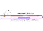
Assume you’re designing a zone circuit for a house. That area consists of three adjacent bedrooms located on the opposite side of the house from where the mechanical room is located. These bedrooms will be heated with series-connected finned-tube baseboard. You’ve done the heat load estimate for the bedrooms and came up with a total design load of 18,000 Btu/hr. You’ve also looked at how the piping will be routed, and estimate the circuit will contain about 200 feet of pipe and 20 90-degree elbows. Your task is to take this situation from load to circulator.
Step 1 - Select a “target” temperature drop for the circuit. The customary value in the North American hydronics industry is 20 degrees F. However, circuits can be designed to operate with higher or lower temperature drops. What are the trade-offs? A higher temperature drop lowers the circuit’s flow rate requirement, but also may increase the amount of fin-tube required. A lower temperature drop does just the opposite. For this example, we’ll stick to a 20-degree F circuit temperature drop.
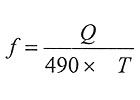
Formula 1

Q = required rate of heat transfer (Btu/hr)
∆T = circuit temperature drop (degrees F)
490 = a constant based on using water in the circuit. Use 479 for 30 percent glycol, or 450 for 50 percent glycol.
Putting the numbers into Formula 1 yields:
Let’s call this the “target flow rate.” It’s the flow rate that would theoretically give you a circuit temperature drop of exactly 20 degrees F when the load is exactly 18,000 Btu/hr. However, depending on the piping circuit and the circulator you select, the actual circuit flow rate might be a bit above or below this value. In other words, you may not hit the center of the bull’s eye, but you won’t know this until you complete the procedure.
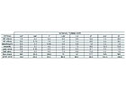
Step 3 - Select a pipe size. This is just a matter of selecting a pipe that can accommodate the required flow rate while operating at a flow velocity between 2 to 4 feet per second. The lower end of this range ensures that air is entrained along with the flowing water (and eventually carried to an air separator). The upper end of this range ensures the noise level of the flow will be acceptable. To find one or more pipe sizes that meet this criteria, just use the data given in the first three columns of Figure 2. In this case, a 1/2-inch type M copper tube will work just fine.

From Figure 3, the equivalent length of a 1/2-inch x 90-degree elbow is 1 foot. So the total equivalent length of the circuit is 200 + 20 = 220 feet.

Formula 2

HL = head loss of circuit in feet (feet of head)
k = a constant based on the fluid and pipe size
(see right column of Figure 2 for k values based on use of water at average temperature of 140 degrees F)
L = total equivalent length of the circuit (feet)
f = flow rate through the circuit (gpm)
1.75 = an exponent of the flow rate
You now have values for all the parameters in Formula 2, so run them through your calculator:
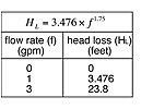
You can also use Formula 2 to estimate the circuit’s head loss at different flow rates. Just make up a table like the one shown in Figure 4. Pick one or two arbitrary flow rates above and below the target flow rate, and plug these number into Formula 2 to determine the corresponding head loss. Keep in mind that the head loss of any piping circuit is zero feet of head at zero flow rate.
The yellow dot on the graph is the target operating point. The black dots are the flow rates and head losses calculated in Step 5. A blue curve (the system curve) has been smoothly drawn through these points.
The other curves on the graph are pump curves for three different “candidate” circulators. Two of the curves pass above the target operating point, and one passes below it.
So which of these three circulators is the “right” choice?
Before answering this, let’s put things in perspective. Based on the information given, you’re trying to hit the center of the bull’s eye at a target flow rate of 1.84 gpm. However, just as in hunting, you don’t always have to hit the center of the bull’s eye to take home the prize.
The flow rate at which this circuit operates depends on which circulator is installed. That flow rate is found by locating the intersection of the blue system curve with each of the pump curves, and then evaluating the results.
Drawing a line down from the intersection of the system curve with the pump curve for circulator No. 1 indicates a flow rate of about 2.25 gpm. Although it’s higher than the target flow rate of 1.84 gpm, it’s not “way off.”
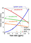
Finally, the estimated flow rate that circulator No. 3 would maintain in the circuit is 1.54 gpm. That is about 16 percent under the target value of 1.84 gpm, but not necessarily a disqualifying shot.
So back to the earlier question: Which circulator is the right choice? Fortunately, any of them would result in acceptable system performance. If you pick circulator No. 1, the circuit will operate at a temperature drop slightly less than 20 degrees F, and you might be able to drop a foot or two off the total length of baseboard in the zone. If you pick circulator No. 3, just the opposite would occur. The circuit will operate as slightly more than 20-degree F temperature drop, and you might have to add a foot or two of baseboard.
About now most of you suspect I’m leading you right to the selection of circulator No. 2. Well, that would be fine, and the system would indeed operate very close to the design goal of delivering 18,000 Btu/hr with a 20-degree F circuit temperature drop. But before you go grab circulator No. 2, there’s one more thing you should consider. If you’ve been following this column over the last several months, you probably already know what that is. If not, I’ll tell you: circulator operating cost.
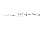
In the system’s first year, the additional operating cost of circulator No. 2 relative to circulator No. 1 would be:
Keep in mind, these numbers are forone small circulator. Suppose you had another five to 10 of these hanging on the mechanical room wall, each pumping heat to other zones with similar wattage and operating hours?
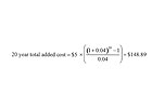
So, if this zone circuit we’re analyzing were your house, which option would you choose: a couple feet of additional fin-tube baseboard, or about $150 higher electrical cost over a 20-year system life? I would go for the small circulator and add the baseboard. Not only is it less expensive, it uses less energy, and thus you could say it’s a “greener” choice. The smaller circulator might even reduce your installation cost by a few bucks.
I’m sure some of you might choose otherwise, and that’s OK. The system is going to work just fine and certainly stay above the callback threshold. It’s very unlikely the owner will ever ask you if you selected the most economical circulator for his system. After all, do the customers ask if the guy who designed the safety controls for the ignition system on the boiler you selected made the right selections? Nah. Do they ever ask if the pressure relief valve you installed on that boiler was the right choice? Nah.
Is it they just don’t care, or could it be they trust you as a professional to do the best possible job when selecting all their hardware? Chances are it’s the latter, and as the holder of that trust, I hope you’re willing to invest more in the circulator selection process than simply “whatever’s on the truck.”
