The way he phrases the question implies he knows that residential heating systems usually use less powerful circulators than do commercial systems. But how small can he go, or perhaps more relevant to his design philosophy - how cheap can he go?
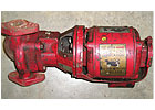
Take a look at Figure 1. This is a familiar sight in basements of older homes in traditional hydronic heating markets. A typical three-piece circulator like this weighs about 26 pounds and requires about 185 watts of power at full load. When it finally spins its last, this mass of metal makes a great anchor for a fishing skiff. Just be sure to drain out the oil before throwing it overboard.
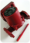
A few decades later, a circuit of similar heating capacity would probably use a nominal 1/25 horsepower wet-rotor zone circulator weighing about 6 1/2 pounds and operating on 60-90 watts. An example is shown in Figure 2.
Water Watts
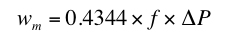
It’s hard to say if the wattage of past or current generation circulators is “where it needs to be” without knowing the mechanical wattage needed to move flow through a specific circuit. This can be calculated using Formula 1:
Formula 1
Where:Wm= mechanical power required to maintain flow in circuit (watts)
f = flow rate in circuit (gpm)
∆P = pressure drop along circuit (psi)
0.4344 = units conversion factor
For example, how much mechanical power is necessary to sustain a flow of 180-degree F water flows at 5 gpm through a circuit of 3/4-inch copper tubing having an equivalent length of 200 feet?
The solution: The head loss associated with this flow is 9.11 feet. You could look this up in a number of references or calculate it using a number of computer programs. The pressure drop associated with this head loss is 3.83 psi. Putting these numbers into Formula 1 yields:
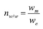

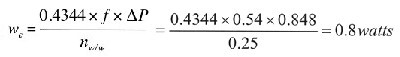
Formula 2
Where:nw/w= wire-to-water efficiency of the circulator (decimal percentage)
wm= mechanical power transferred to water by impeller (watts)
we= electrical power input to motor (watts)
Formula 1 and 2 can be combined into Formula 3:

Formula 3
A current generation wet-rotor circulator has a maximum wire-to-water efficiency in the range of 25 percent. If we put this into Formula 3 along with the previous data, we get the electrical wattage required to maintain flow in the circuit.Keep in mind that this wattage is based on the peak efficiency of the circulator, which typically occurs when the operating point is near the middle of the pump curve. Systems that force the operating point higher or lower on the pump curve cause the efficiency to drop.

Say Watt!
Next, consider that a flow of 5 gpm in a circuit with a 20-degree F temperature drop is moving about 50,000 Btu/hr., and the electrical power to “run the conveyor belt” according to the last calculation is only 33.2 watts. The distribution efficiency of such a circuit is:
These numbers imply that the hydronic system delivers heat to the building using only 2.9 percent (e.g., 44.4/1,506) of the electrical power required by the forced-air delivery system.

From Small To Micro
This comparison shows that the electrical power needed to transport heat throughout a building using hydronics is already a pittance relative to that required by a typical forced-air system. But is this as good as it gets? Is it possible to use even less power and still have a functional hydronic system? As you’ll soon see, the lower limits on circulator power may just start with a decimal point rather than a digit.For example, consider a circuit of 1/2-inch
PEX-AL-PEX tubing transporting heat to a panel radiator that delivers 8,000
Btu/hr. to a 16 x 20 foot bedroom at design load. Suppose the equivalent length of the circuit is 200 feet (50 feet supply
tubing + 50 feet return tubing +100 feet equivalent length of the panel
radiator). With the panel operating at a 30-degree F temperature drop, the
required flow rate is:

Next, consider a 250-foot-long radiant floor circuit of 1/2-inch PEX tubing embedded in a bare concrete floor at 12-inch spacing and supplied with 110-degree F water. At 0.75 gpm, that circuit supplies 6,656 Btu/hr., and has a nominal 18-degree F temperature drop. The pressure drop along this circuit is 2.66 psi. Assuming the same 25 percent wire-to-water circulator efficiency, the electrical power needed to sustain this operating condition is:
Although significantly higher than the previous result for the panel radiator circuit, this is still a tiny number compared to what typically comes to mind when we think circulator wattage.
The point of these calculations is to convince you that the electrical power needed to move flow through typical residential hydronic circuits is very small.
Anticipation
Imagine you could buy a “microcirculator” that operates in the range of perhaps 0 to 5 watts. You could use one on each homerun circuit to a radiant floor panel, panel radiator or baseboard. Heat output to each circuit could be precisely regulated from zero to full design load by varying the speed of the microcirculator in response to room temperature. In the case of panel radiators, you could send 80,000 Btu/hr. to a house under design load conditions using about 8 watts of electrical power to make the delivery.Pie-in-the-sky, you say. Who in their right minds would make such a tiny circulator and really expect there’s a market for it? Hint: Where do we usually look when it comes to “think-drastically-outside-the-box” hydronic concepts? You got it - the Europeans.
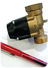
Take a look at Figure 3. The device at the bottom is a pen. What do you suppose the device above the pen is?
For now I’m going to keep you guessing. I don’t want to spoil the surprise when these appear at your local wholesaler in the not-too-distant future. For now, let’s just say this device is a real hydronic system component. It weighs a few ounces. Several of them are operating quite nicely in European systems. And each of them draws less power than a typical Christmas tree bulb.
Happy guessing.
