
I have a friend who is a seasoned fire protection professional with 40 years of experience with automatic fire sprinkler systems. He holds a Bachelor of Science degree in physics and knows everything there is to know about fire sprinkler systems. When I asked him what he thought was the most daunting problem facing the industry today, he pointed out two facts:
- A diminishing number of fire sprinkler designers actually know how to hydraulically calculate a system.
- Very few fire sprinkler system plan reviewers know what they are looking at when reviewing hydraulic calculations.
I absolutely agree with his assessment. With the growing ease of using software to do this work, it is precariously easy for a technician to unwittingly enter inaccuracies into the computer if he is incapable of recognizing the error. Add a hydraulically challenged plan examiner into the mix, and presto - you have a recipe for junk.
What muddles matters further is the annoying paper jungle that a computer will produce after the technician clicks the print key. You may guess that someone designed the computer program in a way to maximize the final product of cluttered and jumbled arrays of nodes, figures and redundancies. You may be right.
Basic Job
Recently it was my job to review a fire sprinkler shop drawing and accompanying hydraulic calculations. The project was very basic, consisting almost entirely of brass upright sprinklers protecting a storage warehouse. In the jargon of the fire protection industry, this is your classic “box job,” consisting of a flat roof, non-combustible construction, two very small offices, several overhead garage doors, four walls and not much else.This project can be hydraulically calculated using a standard computer program in a short amount of time. Generating a hydraulic calculation for this type of simple system is such smooth sailing that it would take a seasoned design engineer maybe 10 extra minutes to do the hydraulics by hand, using hydraulic data tables.
Although that work is tedious, I like two things about “hand-made” calculations:
First of all, they give the designer more freedom to do what he wants with the piping design while he is calculating.
Secondly, hand-made calculations are very easy for the reader to follow and/or review.
But the facts are that computer-generated hydraulics have a better professional “look” about them, inputted data notwithstanding. And certainly, when calculating loops or gridded systems, the computer program will literally shave hours off the task. Finally, the computer program quickly accomplishes the iterative process of using velocity pressures.
The calculations I reviewed for the box job were, like most calculation programs, overly prolific with numbers. So prolific that the calculations themselves seemed oddly ordered and hard to follow. Eight pages, for example, were submitted for a single calculation for this very basic job.
In other words, the fluff easily outnumbered the substance. The reader is treated to an endless litany of repetitive aggregate flow analysis, redundant node tags and pipe references numbered in two different ways. That confusing “fluff” proves nothing beyond the fact that the software program has not been set up to keep things simple.
A complete and concise hydraulic calculation for such a basic system should only take three pages to make the information clear, whether it is done by hand or computer. And that includes the cover (hydraulic summary) sheet and the page (N1.85 graph sheet) that plots the system demand point.
An Example
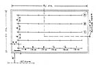
I want to illustrate this by using the sprinkler drawing shown in Figure 1, which depicts a hypothetical automobile repair garage. A small wet-pipe “tree” system protects the building, with one 4-inch cross-main supplying five branch lines hung from a 15-ft. flat roof. The upright sprinklers have a K-factor of 8.1, and the header consists of an 8 x 4 reducing flanged elbow, two OS&Y valves, backflow preventer, flanged tee and Schedule 40 riser. The elevation of the highest sprinkler deflector is 14 ft. Dimensions shown between piping and sprinklers are center-to-center. The riser nipples are 2 x 1-0 center-to-center. Branch lines consist of Schedule 40 black steel piping and 125-lb. cast-iron fittings.I realize that we could use a pipe schedule system here, per Sections 11-2.2 and 14-5 of NFPA 13 (2002 ed.). But for this example, I have run the calculation shown in Figure 2. It is easily contained on one piece of paper. It is perfectly acceptable, and all that you need to prove hydraulic adequacy.
If you have a copy of the current NFPA 13, you would first turn to page 209 to peruse occupancy examples and determine the level of hazard (in this case Ordinary Hazard Group II).
You would then turn to page 100 to examine the area/density curves. The lowest point on the curves is normally used, and here the appropriate curve yields the design density of 0.20 gpm/sq.ft., over a 1,500-sq.-ft. “area of sprinkler operation.”
We could also select a design area of 2,000 sq. ft., resulting in a required design density of 0.19 gpm/sq.ft. However, choosing the smallest (hydraulically remote) design area is the most economical option, since a larger gpm demand will almost always result when a larger design area is selected.
Twelve sprinklers are being opened in this example, and each covers 130 sq. ft. Technically, this means that our area of sprinkler operation is really 1,560 sq. ft. Therefore, you could use 1,560 sq. ft. as your design area, and referencing Figure 11-2.3.1.5, interpolate a design density of 0.198 gpm/ sq.ft., and still be going correctly by the book. We know that we need to open at least 12 sprinklers in the calculation because 11 ft. times 130 ft. equals 1,430 sq. ft., which is less than the required (1,500-sq.-ft.) area.
The shape of the remote area shown in Figure 1 is supposed to have a dimension parallel to the branch lines of 1.2 times the square root of the (1,500-sq.-ft.) design area. As a result, it will always yield an area rectangular in shape. The longer the dimension parallel to the branch lines, the more conservative the design area.
When an insurance company or some other authority asks for a factor of 1.4 in lieu of 1.2, they are just enforcing a requirement that is in excess of the (minimum) standards noted in NFPA 13. At any rate, the selection of the correct “physically remote” area is extremely critical. In this simple example, the remote area is easy to ascertain, so the potential for error is low.
Another way to pinpoint how many sprinklers on each branch line should be calculated would be to multiply 1.2 by the square root of 1,500 (1.2 X 38.7 = 46.4) and divide that (46.4) total by the distance separating the sprinklers (13 ft.). This leaves a number of sprinklers (3.57) that must be rounded up, which in this case means four sprinklers should be opened per line.
Once these parameters have been established, we can run our branch line calculations. In this case, all branch lines are identical, and therefore, one line calculation will suffice. (See Figure 2.) Please note that following Head No. 4, we are flowing 119.59 gpm back through the 2-inch pipe to the cross-main. The “effective length” noted is 58.5 ft. This is in compliance with requirement 7 under NFPA 13:14-3.3 for detailed work sheets on hydraulic calculation forms.

To The Point
If you want to get fancy, you could scrawl in the fact that the equivalent lengths for the two 2-inch tees (at the top and bottom of the riser nipple) are included in this effective length. But I'm sorry: If a plan reviewer cannot figure out that the 58.5 total refers to 38.5 ft. of pipe plus the 20 equivalent feet for the two tees, then he should probably look for another line of work.The computer balances the gpm demands for each additional branch line as it “flows” the water demand down the cross-main. The gpm total added for each line should be at least equal to the (119.59) total for the branch line calculation. And most definitely, the total gpm demand should exceed the (0.20 X 1,500 = 300 gpm) basic design density equation.
Without splitting hairs, we know that we will lose 6.06 psi raising the water to the required 14-ft. elevation to the sprinkler heads. The exact inside pipe diameter for the 4-inch header and riser is noted, and it is smaller than that of the cross-main since the pipe wall is thicker for the threaded 4-inch Schedule 40 piping vs. the thinwall cross-main.
The calculation flows the accumulated gpm demand out to the city water main. The C-factor changes for the Class 52 ductile iron underground pipe to 140 (see NFPA 13 Table 14-4.4.5). As a result, we have to make sure that what we input for the underground fittings incorporates the higher effective fitting length factor noted in NFPA 13 Table 14-4.3.2.
Finally, the additional friction loss incurred through the backflow preventer must be inputted, and this data has been taken directly from manufacturer's data sheets. Or, this can be documented from the friction loss test curves taken by Underwriters Laboratories or some other testing agency. In either case, the inclusion of a copy of such documentation would be a substantial addition to the submitted calculations.
The example calculation finishes with a statement eliciting total system demand, including hose streams. And that's the whole idea: to most accurately determine the demand that must be satisfied by the available water supply. The entire submittal can consist of this single sheet, plus the hydraulic summary sheet and the graph.
While this approach is not flashy, it's to the point. And keeping things to the point makes the plan review process more expedient.
Certain Authorities Having Jurisdiction (AHJ) will require a psi “cushion” of some stated amount between the system demand point and available pressure. Even if they do not, I would make a habit of leaving a safety buffer of 3-7 psi out of principle, just because economics are not the only criteria of quality design. The typical installed sprinkler system rarely goes in exactly as designed, and so piping offsets necessitated by field conditions will not be reflected in the hydraulic calculation. Neither are future system modifications made during facility remodeling, so it is prudent to be a little conservative from the get-go.
When an eight-page hydraulic calculation can be trimmed to three pages, I hope an AHJ somewhere wouldn't be so shortsighted that he thinks a designer is taking shortcuts.