Again, whenever you look at wires in walls or drawings of them, what you're seeing is the cables that contain the wires. It appears that there are a few big fat wires. Actually what counts are the smaller wires inside the cables.
When you're looking at cables, it appears that there's one wire coming from the service panel, and none going back. The fact is that inside the cable are at least two wires. For simplicity's sake, I'll write here about two wires, even though in construction done in the last 40 years, there are three - one for grounding.
Click to view larger photo.
Wiring Switches And Loads: A switch is connected in a different way from a wall outlet. Only the hot wires are connected to a switch. That's because the switch “breaks only the hot leg” of the circuit. Remember that “breaks” means “turns off,” or creates an opening like the drawbridge.
The neutral leg doesn't need to be broken, or turned off. That's because it carries used-up electricity back to where it came from.
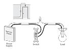
A wall switch has three terminal screws. Look at the pair of terminals on the right side of Figure 1. One terminal is for the hot electricity to come in, and one is for it to go out. If the switch is closed (turned on), the electricity passes through the switch as if the switch was not there.
If the switch is open (turned off), it stops the electricity.
Figure 1 shows how switch wiring looks if the switch is installed between the power supply (service panel) and a load (ceiling light). Notice that there's a complete circuit of the service panel as power supply, the wall switch as switch, and the ceiling light bulb as the load. (Another way to look at it is that the power plant is the power supply, the service panel is the first switch, the wall switch is the second switch, and the light bulb is the load.)
There are wires from two different cables coming to the switch. The black wire from each cable is connected to one of the terminal screws. The white wires from the two cables are connected to each other. They aren't connected to the switch at all. Electrically this means that the used-up neutral electricity in the white wire goes around the switch, and back to the service panel.
Click to view larger photo.
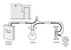
Here's what's different from Figure 1. The switch always needs to be in the “hot leg.” That usually means it will have two black wires connected to it, and no white wires. But a cable has only one black and one white wire. When the switch is “at the end of the run,” only one black and one white wire are available. In that situation, the electrician uses the white wire as if it were black, to bring power to the switch.

Click to view larger photo.
Grounding The Switch And Fixture: The grounding terminal is the third screw on a switch. (See Figure 3.) The grounding terminal stands by itself and is bare copper or colored green. Older switches aren't grounded. More recently, the grounding wire is wired to the switch like to an outlet. If the switch box is metal, the grounding wire is connected to both the switch and the box. A “pigtail” is used to make the connection. A grounding wire is also attached to the light fixture.

Click to view larger photo.

Click to view larger photo.