
Click to view larger photo.
Those who've worked within the hydronic radiant heating market in most areas of the county have probably been asked about the feasibility of snowmelting. Many hydronic professionals now offer it as a part of their repertoire. It's a natural extension of the skill set learned to design and install radiant heating systems.
Still, the differences between radiant floor heating and snowmelting go far beyond whether the tubing is inside or outside a building. Failure to recognize key design concepts associated with snowmelting can lead to very disappointing results and costly corrections. This month we'll discuss a few strategies that I think are important in designing successful snowmelting installations.
1. Always, always, always plan for pavement drainage.
Installing snowmelting without proper drainage is like doing an indoor pool without a dehumidifier; both reduce cost and both will quickly get you in big trouble.The idea is to melt the snow and ice and then allow most of the water to drain away rather than evaporate or refreeze. Changing snow into water requires about 144 Btu/pound. Assuming a 6-inch-thick layer of newly fallen snow with a density of about 10 percent water, a system would need to provide 448 Btu/sq. ft. of pavement to fully melt that snow into water at 32 degrees F.
However, evaporating that water requires about 970 Btu/pound - almost seven times more energy than needed to melt the snow into water. Some of this evaporation energy comes from the atmosphere, depending on relative humidity and air temperature. Still, having to operate the snowmelting system for a prolonged “post-melt” period just to evaporate water that hasn't drained from the surface is expensive. The alternative of turning the system off before the pavement is dry is even worse. Doing so can turn a wet surface into glare ice. Run that option by your insurance carrier.
Always slope pavement surfaces toward drains, and be sure those drains lead the melt water to where it will not freeze. In locations without storm sewers, this may require drywell(s). Be sure you assess the drainage requirements when discussing snowmelting options with clients. Be sure you communicate who is responsible for such drainage in your proposals and contracts. Keep in mind that the drainage system will also have to handle heavy rainfall events during warmer weather.
2. Consider off/manual/auto selector switches as part of the snowmelt control system.
There may be times when snow needs to be melted and it's not snowing outside. A patio or walkway at a weekend house is a good example. Perhaps it snowed when nobody was home, the snowmelting system was turned off to save fuel, and upon arrival there's a foot of snow on the walkway that needs melting.These situations can be handled with a simple selector switch for each snowmelting zone. The “off” setting disables snowmelting. The “manual” setting turns it on and leaves it on. The “auto” setting puts melting under the control of the snow/ice detector system. Figure 1 shows an electrical schematic for this concept.
The “manual” mode usually requires the owner to remember to turn the system off. Forgetting to do so could obviously lead to some pretty high fuel bills. As a hedge against this, consider installing a timer circuit that disables melting in the manual mode after a period of 12-24 hours of operation. If there's still snow to be melted, the owner can dial in additional operating time as necessary.
I also like the idea of a prominently located indicator light that remains on when the system is in melting mode. This should prompt someone who's set the system in manual melt mode to reset the selector switch before leaving the building for several days.
Click to view larger photo.
3. Never exceed 12-inch tube spacing.
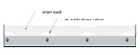
Although it's possible to get acceptable performance in some floor heating applications using 18-inch or even 24-inch tube spacing, this is not the case with snowmelting. Tubing spaced wider than 12 inches will cause “tenting” as the snow melts. In effect, the warmer pavement surface directly above the tubing creates small elongated igloos in the snow (see Figure 2). The air trapped between the snow surface and pavement then decreases the rate of further melting.The following tube spacings are suggested, depending on the class of the snowmelting application:
• Class 1 systems - residential applications; 9 inches to 12 inches.
• Class 2 systems - high melt rate residential/commercial; 6 inches to 9 inches.
• Class 3 systems - critical applications where pavement must remain snow free at all times; 4 inches to 6 inches.
4. Remember that flow is critical for heat delivery.
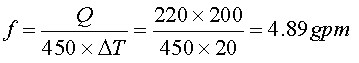
A radiant floor heating system at design load conditions may deliver around 35 Btu/hr./sq. ft. In contrast, a Class 2 snowmelting system in a location like Buffalo, N.Y., needs to deliver about 200 Btu/hr./sq. ft. If one assumes the same temperature drop on both circuits, the difference in heat delivery must be handled by increased flow rate, and this usually requires larger tubing.Here's an example. A 220-ft.-long snowmelting circuit with tubing spaced 12 inches apart must deliver 200 Btu/hr./sq. ft. at design load. The circuit operates with a 50 percent solution of propylene glycol and has a design temperature drop of 20 degrees F. The required flow rate can be seen in Formula 1.
Don't even think about trying to shove this through 1/2-inch or 5/8-inch PEX. You'll need at least 3/4-inch tubing to handle this flow rate at a reasonable head loss.
By the way, the head loss of a 220-ft.-long circuit of 3/4-inch PEX carrying 50 percent propylene glycol at 4.89 gpm is 34.5 ft. That's pretty much out of the range of small wet rotor circulators. Changing the circuit to 1-inch PEX at the same flow rate drops the head loss to 10.5 ft.
5. Protect against condensation.
If a conventional boiler is used as the heat source for a snowmelting system, it must be protected against sustained flue gas condensation. This is easily handled by a modern mixing system with boiler inlet temperature sensor.However, when the fluid your system is handling is literally “ice cold” at start-up, you also need to protect against condensation and frost in other parts of the system. Here's what to keep an eye on:
• All interior piping serving snowmelt manifold stations should be fully insulated and vapor-sealed to prevent surface condensation. Don't get sloppy at pipe supports and valves. Be sure the insulation runs through the pipe supports with the necessary support sleeves, and that it also surrounds valve bodies. If not, you'll surely see dripping and rusting hardware in short order. Also, be sure the butt ends of the insulation are bonded together.
• Insulate the circulator volute, or locate it where condensation dripping from it will not be a problem. Also position the junction box on a wet-rotor circulator carrying cold glycol at the top of the motor to keep it as warm (and condensation-free) as possible. Another option is to use a nonwet-rotor circulator with a coupling assembly to keep the motor warm enough to prevent condensation.
Click to view larger photo.
5. Protect heat exchangers against freezing.
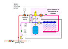
Consider the piping shown in Figure 3a. It can be used for small snowmelting applications such as steps. It can also be used for garage floor heating. It uses one less circulator compared to the more typical snowmelt piping detail shown in Figure 3b. However, there is an Achilles heal that must be addressed.
Imagine a situation where the boiler is starting from room temperature at the same time the snowmelting distribution circulator starts. Also assume that the incoming glycol is at an outdoor ambient temperature of 10 degrees F. See any potential problems? If not, here's a hint: The “warm” side of the small flat plate heat exchanger may contain less than a pint of water. Do you see the “race” shaping up?

Click to view larger photo.
The boiler, which has now warmed to normal operating temperature, is of little help at this point since flow through the heat exchanger is blocked. The system will remain in an unsatisfied call for snowmelting for several hours. The “dead headed” injection circulator might even be damaged by then.
One way to avoid this scenario is to install a setpoint control that verifies the water leaving the heat exchanger is up to some minimum temperature (say 110 degrees F) before allowing the snowmelt distribution circulator to operate. If something happens to the heat delivery system and the water leaving the heat exchanger drops to 80 degrees F, the distribution circulator is disabled before the heat exchanger could freeze. This same freeze protection can also be used with the piping shown in Figure 3b. It's good insurance against a ruptured heat exchanger in the event of boiler lockout.
Click to view larger photo.
6. Always insulate under heated pavements.
It's the same reasoning as a heated floor slab. The idea is to direct the heat where you want it (e.g., the top of the pavement) rather than into an almost infinite heat sink (the earth).You only get one opportunity to do it right. Use a proven product like 25 psi or higher rated extruded polystyrene, and always install it on properly tamped subgrade. If the concrete pavement could have heavy commercial vehicles on it, I suggest a minimum of 60 psi rated extruded polystyrene.
Leave some small gaps between adjacent sheets of insulation so the water that inevitably percolates down through cracks in the pavement surface will not be trapped above the insulation where it could refreeze and heave the pavement. Be sure there is high percolation soil or bed of gravel under the insulation to allow this water to dissipate rather than “pond” under the insulation.
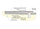
If you're asked to do snowmelting under a driveway with pavers, I suggest the detail shown in Figure 4. It uses a concrete slab to contain the tubing as well as provide a stable structural layer between the pavers on stone dust and the foam insulation. Without this layer, there is concern over differential settlement of the foam due to high loads in tire track areas. The top of the slab is sloped to allow water to drain out of the stone dust layer rather than refreeze and heave the pavers.

Click to view larger photo.
7. Consider a minitube injection system.
If you're doing a system where there's significant distance between the snowmelt manifold station and the mechanical room, consider supplying that manifold station using a minitube system as shown in Figure 5.
This approach has the added benefit of keeping the snowmelt distribution circulator, and its associated operating noise, at the manifold station. It also reduces the size of interior tubing that must be insulated against condensation. Minitube injection systems using pre-insulated direct burial piping have been successfully used in large (multimillion Btu/hr.) snowmelting applications.
8. Lift the tubing to mid-slab height during pour.
The transient response of an ice-cold concrete slab is slow enough without extra inches of concrete between the tubing and top of slab. Be sure to communicate how important this is to those responsible for placing the concrete. Make sure it's clearly described and drawn in your documentation. Provide a detail for control joints that keep the tubing down under the saw cuts.9. Identify possible drifting locations.
If the pavement being melted includes areas where snow drifting is likely, consider zoning the system. Drifted areas often require longer melting times relative to sheltered areas. Why run the entire snowmelt system if only certain portions of the pavement need this longer melting time?
Zoned systems are best controlled with in-slab snow detectors rather than above-pavement snow-switches. It's important that any automatic snow detectors be placed to reflect likely drifting patterns. Think about prevailing winds and vertical surfaces, such as retainer walls or shrubs that rise above the upwind side of the paved areas. Drifts can also form at the downwind corners of buildings located adjacent to pavements. Snow can pile up just outside the overhang line of roofs located upwind from the pavement. Plan your zones accordingly.
Click to view larger photo.
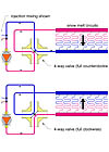
10. Consider a four-way flow reverser valve and higher circuit temperature drop.
Consider a four-way flow reverser valve and higher circuit temperature drop. Anyone who's ever watched a heated pavement melt snow has seen that melting occurs faster above the supply end of the embedded circuit(s). In some systems you can take advantage of this by placing the supply side of snowmelting circuits under the more “critical” areas of the pavement, such as tire tracks or walkways.However, for larger paved areas, it's preferable to melt the snow at approximately the same rate. This can be encouraged by counterflow spiral circuit routing. It can also be enhanced by periodic flow reversal through the tubing circuits using a four-way valve body and two-position actuator as shown in Figure 6.
Flow reversal is described in more detail in the April 2004 Hydronics Workshop column (“The Long Way Around”). This concept allows for longer circuits operating at higher temperature drops while also promoting more even melting patterns. Higher temperature drops enable more heat to be carried on the same flow rate, and thus should allow for reduced pumping volume, circulator size and operating cost.

