
Like other systems of that vintage, it contained hundreds of segments of 3/4-inch copper tubing and at least as many 90-degree elbows. Someone spent a lot of time measuring, cutting, cleaning, fluxing and soldering all that copper together. My guess is that they were probably paid something like $2 to $3 per hour to do so.
Short of finding a new Thatcher fire-tube boiler, you could duplicate that system today. You could still solder all that copper tubing together, still install a tankless coil for DHW, and still pump into the boiler. The newly minted system would still experience the effects of decreasing water temperature from one series-connected baseboard to the next. The room at the end of the circuit would still be cooler than the room at the start of the circuit. Those new baseboards would still produce the familiar ticking sounds as hot water raced through cool piping at the start of each heating cycle. Oh, and you could still expect an occasional call to bleed air from that new system.
Most seasoned "hydronicians" (as Mark Eatherton calls them) know that the methods and materials they now use increasingly differ from those used by a previous generation of heating professionals. This is not a put down of the systems designed and installed by our predecessors, it's an acknowledgement that the technological possibilities associated with hydronic heating continue to advance.
At the same time, issues such as labor costs and skill level demand frequent re-examination of design and installation options. Those who plan a profitable career in hydronic heating must keep pace with these changes. It's certainly true with hydronic radiant heating, and it's also true with the more "pedestrian" hydronic heat emitter - fin-tube baseboard. This month we'll exam ways to enhance the performance and versatility of fin-tube baseboard systems, and see that you can indeed teach an old heat emitter new tricks.
Why Relive The Past?
Traditionally, most residential baseboard systems are built using series piping circuits. Although simple in concept, series circuits always produce temperature drops from one baseboard to the next. If this effect is not properly factored in during design, the result will be overheated rooms near the beginning of the loop and underheated rooms near the end, especially on long circuits. Series loops also severely limit the ability to zone systems or balance heat output to compensate for internal heat gains. Long series circuits can also produce high head loss and reduced flow rates that, in turn, reduce thermal output.Parallel-piped systems offer far fewer nuances. Because each branch circuit receives the same water temperature, it's easy to select a design supply temperature and size each heat emitter based on it. Gone is the need to compensate for temperature drop from one baseboard to the next. Parallel systems also allow the flow through each branch to be individually controlled, and thus allow for easy zoning and balancing.
Although parallel-piped baseboard systems can be constructed using rigid tubing, a faster and more flexible approach is a "homerun" system using PEX or PEX-AL-PEX tubing (see Figure 1). The baseboard in each room is individually supplied from a common manifold station just like those used for radiant floor heating.
Homerun systems typically use more linear feet of tubing than do series loops, but that small flexible tubing goes in fast and easy, especially in new construction. In retrofit jobs, small flexible tubing greatly reduces the need to open existing walls or ceilings to install piping, often allowing installation options not possible with rigid tubing. I often tell people that if they can route an electrical cable from point A to point B in the building, they can also likely route two lengths of small flexible tubing between those same locations.
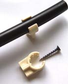
C-shaped CPVC tubing support clips (see Figure 3) in combination with 1/2-inch PEX-AL-PEX tubing work great for homerun circuits. One screw holds the clip to the framing. The tubing just snaps into the open end, and can easily slide back and forth due to thermal expansion/contraction. The aluminum core in PEX-AL-PEX tubing makes it easy to hand-form the tubing to the required shape, and helps it stay in that shape once uncoiled.
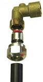
When the tubing runs reach the baseboard, just hand-form the needed bends and pop the tubing up through holes sized 3/8-inch larger than the OD of the tubing. The oversized holes accommodate expansion movement of the fin-tube element without binding the tubing against the subflooring. For a professional appearance, slip a small escutcheon plate over each tube before connecting it to the baseboard fitting. In total, you'll make two soldered joints and two wrench-tightened joints at each baseboard, a far cry from the 16 soldered joints often required when rigid piping and 90-degree elbows are used.
A Few More Amenities
To get the most out of baseboards supplied by a homerun distribution system, you'll want to include a few more details, including:- Room-by-room zoning controls;
- Outdoor reset of supply water temperature; and
- Differential pressure control.
To smoothen system response and keep the distribution system as quiet as possible, you'll also want to regulate the water temperature supplied to the manifold(s) using either boiler reset control or mixing reset control.
Boiler reset control is simpler and less expensive than mixing reset control. It also has a proven record of reducing fuel costs. However, conventional gas- and oil-fired boilers require protection against sustained flue gas condensation, and thus limit how low the boiler reset control can operate. Supply temperatures of less than 140 degrees F should not be used unless the boiler manufacturer specifically states that lower-temperature operation will not harm the boiler. Because of minimum boiler temperature constraints, there will be times when the TRVs must throttle to very low flow rates to prevent overheating. It is imperative to use differential pressure control to prevent flow noise in such situations.

Keep in mind that several currently available mixing reset controls also provide boiler reset capability as well as the intelligence to turn on the distribution circulator when outdoor temperatures drop below a set threshold temperature (typically around 65 degrees F). They are ideal "system controls" for a homerun system supplying baseboard.
The final component this type of system needs is a differential pressure bypass valve. This valve prevents the circulator from operating at high differential pressure when most of the TRVs or valve actuators are closed. Unchecked, high differential pressure can cause flow noise and increase circulator wear. The shaft of the bypass valve should be adjusted to eliminate any flow noise present when each homerun circuit is operating by itself.
The fully trimmed system concept is shown in Figure 5. Keep in mind that this arrangement could also serve as a subsystem to supply baseboard heating in part of the building while other areas are served by radiant heating. Some of those homerun circuits could also be used to supply panel radiators or heated towel racks
I still consider fin-tube baseboard a "staple" of residential hydronic heating in North America. When enhanced by the modern hardware and design concepts we've discussed, this proven heat emitter delivers even smoother and quieter comfort. You'll notice the difference and so will your customers. Chances are the techniques we've discussed will soon become your "norm" for baseboard installations.
