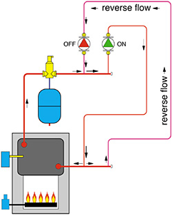
Whenever multiple circulators are piped in parallel, the potential exists for reverse flow through inactive circuits. Figure 1 shows how this can occur. The water, once pushed out the discharge side of a circulator, only cares about getting back to the inlet side of that circulator. It doesn't care if it happens to pass through a heat source to pick up some more Btus on the way back to the circulator.
If it occurs, reverse flow allows heat to be released into zones that are supposed to be off. It also decreases the water temperature supplied to active zones since cooler water can now mix with hotter water in the supply header. Both of these can be real problems.
To prevent this, a check valve must be installed in every circuit that contains a circulator and is connected to a common header.

Gravity Gremlins
A standard swing check installed in each zone circuit will prevent the reverse flow situation just described. However, another quirk is at work trying to validate Murphy's law. Hot water in the heat source, because of its lower density, wants to rise into any zone circuits that travel upward into the building. Just because there happens to be a pump on the loop doesn't mean that loop won't attempt to function as a "gravity" heating loop if given the opportunity.The flapper as a standard swing check has virtually no resistance to slow forward flow. Hot water will slither under the flapper and continue on to warm heat emitters at inopportune times -- like a 95-degree F day in August after the boiler has fired for domestic water heating.
Stopping forward flow requires a device with enough forward opening resistance to keep a lid on the buoyancy forces generated by the hot water. The traditional flow-check valve was developed to provide this resistance as well as providing the basic check valve function. The plug in such a valve requires a pressure of approximately 0.3 psi to lift it off its seat to allow flow in the forward direction.
This is enough resistance to hold back buoyancy forces in a typical residential or light commercial hydronic system, yet is easily overcome when the circulator turns on. Many spring-load check valves have similar "threshold pressures" and thus can be used as an alternative to traditional flow-check valves.
For decades, flow check valves have been installed a separate piping component in each zone circuit. Many are supplied with three ports allowing flow to enter from the bottom or the side. The unused inlet port is simply closed off with a plug.
Although these valves have certainly served their purpose, they undeniably add to system installation time and cost. Each cast-iron flow check typically requires three threaded joints. If the zone piping is to continue vertically upward, at least one elbow will also be required for each flow check.

Two Into One
During the last couple of years, two major manufacturers of wet rotor circulators have introduced models with built in flow-check valves into the North American market. Both manufacturers mount a small, spring-loaded check assembly into the volute of their circulators.This assembly provides the necessary forward opening resistance to block gravity flow (approximately 0.7 feet of water or 0.3 psi). The check assembly also prevents reverse flow when multiple pumps are used in parallel.
These pumps provide the functionality of a separate circulator and flow-check while reducing both material cost and installation time. They also present some new operating characteristics that system designers need to consider.
Chief among these characteristics is a reduced pump curve relative to the same circulator without the check valve assembly. The presence of any component in a flow stream dissipates some of the head energy added by the impeller. The spring-loaded check valve assembly is no exception. To illustrate this, the pump curves for the current-available Grundfos UP15-58 and a Taco 007 circulator both with and without internal flow checks are plotted in Figure 2. These curves are all based on published performance data from Taco and Grundfos.
Notice that both pump curves move down and to the left when internal flow checks are present. The difference between the curves becomes more pronounced at higher flow rates where the head loss through the check assembly is greater.
A pump curve, however, only tells part of the story. To assess the effect on system performance, the pump curve must be overlaid on the system curve for the piping circuit in which it will be used. Figure 3 shows some representative system curves.
The relatively steep (blue) system curve represents a 3/4-inch type M copper tube circuit with a total equivalent length of 250 feet. This might represent a typical series circuit containing several baseboards and a couple dozen elbows. The intersection of this curve with the pump curves for circulators with and without check valves shows there is very little drop in flow rate because of using a circulator with an internal check valve. The drop in thermal performance due to this small decrease in circuit flow rate would be insignificant in most systems.
As the system curves gets shallower, the story changes. For example, the black curve represents a 1-inch piping loop with an equivalent length of about 50 feet. This might represent a simple primary loop in a small system. The intersection of this system curve with the pump curves shows a more significant drop in flow rate when the circulators with internal check valves are used.
This is not to imply that pumps with internal checks should not be used for such piping loops. Rather it shows the need to evaluate the performance tradeoff in higher flow/lower head loss applications.

A Reasonable Question
So how does the performance of circulators with internal check valves compare with that of standard circulators combined with traditional flow check valves? To find out, I plotted the pump curves of the same two circulators (Taco 007 and Grundfos 15-58) along with the head loss vs. flow rate curve of a traditional 3/4-inch cast-iron flow check. The "net effect" is found by subtracting the head loss curve of the flow check from the pump curve as shown in Figure 4. The head loss of the cast-iron flow check is based on curves published by its manufacturer.For the 3/4-inch cast-iron flow check selected, the effective pump curve drops slightly more than is the case with the circulators using internal flow checks. The results will vary depending on the specific head loss vs. flow characteristic of the check valve being used. If you have this data for a particular check valve, just subtract the head loss value from pump curve at a few randomly selected flow rates, and draw a smooth curve through the resulting points. This will be the effective pump curve of the pump plus check valve combination.

Ghost Busters
One nuance of variable speed injection mixing is a very slight "ghost flow" of hot water through the injection risers and nonoperating injection pump into a distribution system that operates with constant circulation. With the proper pipe detailing (very closely spaced tees and a vertical thermal trap as shown in Figure 5), heat migration is very small, but still not zero. With the wrong pipe details, (widely spaced tees and no thermal trap), ghost flow can become a serious problem.Being a zealot against undesirable heat migration in hydronic systems, I'm always looking for ways to eliminate such small but undesirable effects. This led to an experiment in which I installed a spring-load check valve downstream of a variable speed injection pump. I was confident the forward opening resistance of the spring check would stop any ghost flow, but not sure how smoothly the variable speed injection process would work.
When tested, this assembly produced repetitive "thudding" sounds each time a quantity of hot water was pushed through the spring-loaded check valve by the pump. The pump would gradually speed up to increase the static pressure against the closed valve plug until it final popped open. As water began to move through the valve its pressure quickly decreased to the point where the spring quickly forced the plug closed. Thump!
The system did inject the necessary hot water into the distribution system, but in "slugs" rather than a smooth continuous stream. After a couple days of operation, I decided the thudding sounds could not be corrected by further tinkering, and ended up removing the check valve.
After this experience, I was skeptical about using a circulator with a built-in check valve as an injection pump. I did, however, try one such circulator in this application and was pleasantly surprised. The circulator was able to inject hot water with no detectable "thudding" of its internal check valve. Although the injection controller did have to ramp up the speed a bit to open the check assembly, the system quickly and consistently stabilized to the target supply temperature.
Others who have tried these circulators in variable speed injection applications have found similar results, and now routinely use circulators with internal check valves as injection pumps. Although I'm still a big believer in the proper piping details for injection mixing, these pumps do present a solution to thermal migration in systems where such details are not used.
I'm excited about the simplification and economy that can be achieved by using circulators with internal check valves. They lower installed cost without sacrificing performance relative to existing approaches, and are good examples of value engineering. The development of these circulators also points to an industry that's serious about improving the status quo of its technology. I suggest all you hydronic heating pros "check out" what they have to offer.

