
When 1/2-inch tubing is used, circuit lengths should generally be limited to 300 ft. With 3/8-inch tubing, the circuit length should not exceed 250 ft. In larger buildings, these circuit-length requirements result in several tubing circuits spread out across the floor framing.
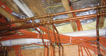

Unbundled
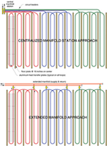
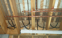
Here's a better approach, one my associate Harvey Youker calls an “extended manifold” system.Instead of a traditional centrally located manifold station with closely spaced tubing connections, install two long copper headers perpendicular to the joists over the full width of the floor. Tap each floor circuit into these headers as they pass by. This almost eliminates “leaders” from where the circuit heats the floor to where it connects to the manifold. A typical arrangement is shown in Figure 4. A photo of an installed extended manifold serving an underfloor tube-and-plate system is shown in Figure 5. A close-up of a typical circuit take-off with ball valve is shown in Figure 6.
The extended manifold approach is not new. Before the days of PEX, it was common to run parallel lengths of steel or wrought-iron piping between tees in supply and return headers. This piping arrangement also has been used in turf heating applications such as when tubing is installed under a football field. The headers run along the sidelines to provide flow for hundreds of laterals running across the field.
When PEX did arrive in the North American market, so did the concept of a centralized manifold station with closely spaced connections. Although this concept works fine for many radiant panel installations, it should not be viewed as a “set-in-stone” installation requirement, especially if it forces compromises in other aspects of the installation (i.e., large bundles of tubing near the manifold station).
Teed Off
Connections to the extended manifold are made using a reducing tee with a ball valve and transition fitting from copper to either PEX or PEX-AL-PEX tubing. Having a ball valve on one end of each circuit is essential for air purging. During purging, all ball valves except the one on the circuit being flushed are closed. This keeps the flow velocity up to quickly force bulk air out of the piping.At least one supplier offers specialty ball valves with the PEX transition fitting on one end. This could certainly speed up installation. The extended manifold system would also be a great place for an as-yet undiscovered hybrid fitting that combines a reducer tee, ball valve and PEX (or PEX-AL-PEX) transition fitting into a single component.
Installing a balancing valve on the outlet end of each circuit allows for flow adjustment. In combination with a ball valve on the inlet, it also allows each circuit to be isolated from the extended manifold if necessary.
When individual circuit control is needed, a zone valve could be installed on the supply side of each circuit. Be sure to install a differential pressure bypass valve when several zone valves are used.
Keep the extended manifold piping “generously sized” to minimize the pressure drop along its length. I suggest sizing the manifold piping segments for a flow velocity of 2 to 3 feet per second when all circuits are operating.
You can reduce the pipe size of the outer portions of the extended manifold. Just keep track of the flow rate at various locations and size the pipe accordingly. Of course, you can always keep the manifold pipe size constant based on the highest flow requirements. This helps where you want the manifold piping to lie flat along a surface and don't happen to have eccentric reducer couplings.

Assuming that balancing valves are present, and that the head loss through the extended manifold piping is small relative to the head loss through the floor circuits, the advantage of reverse return piping is minimal, and probably not worth the added installation expense in this type of system.
If the extended manifolds connect to the remainder of the system piping near the middle of the floor area, you can use a Y-fitting or a couple of 45-degree tees. Although it's tempting to just install a “bullhead” tee in these locations, the Y-fitting or 45-degree takeoffs reduce turbulence, which in turn reduces head loss and operating noise.
Doing The Math
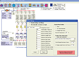
With an extended manifold, the head loss of the piping segments between the circuit takeoff points is higher than with a standard manifold having closely spaced takeoffs. This added head loss should be accounted for during design.When the extended manifolds and floor circuits form a parallel direct-return piping configuration as shown in Figure 4, the piping system can be simulated using the Hydronics Design Studio software. An example is shown in Figure 7.
By turning on the “define header piping” option, you can define each segment of the extended manifold. You can also specify up to 12 parallel floor circuits, including tube type and size, circuit length, and even the percentage of each tubing circuit that contacts the floor surface. You can then select the fluid type, temperature and a circulator. The software calculates flow through all piping segments, as well as the heat transfer from the floor circuits and displays the results. You can quickly change hardware selections and operating conditions to see the overall effect on performance. When circuit-balancing valves are shown, they can be used to fine-tune circuit heat output.
Hydronic radiant heating installations frequently present opportunities for refinement. The extended manifold system is one example of such a refinement. It reduces both tubing footage and installation labor. In the process, it also improves the appearance of installations where most of the tubing runs parallel to floor joists. Keep it in mind the next time you're contemplating wheelbarrow-loads of sawdust from drilling dozens of holes to get tubing circuits back to a centralized manifold.
