
As common as this method of zone control is, it's not the only act in town. An alternative approach that's relatively new to the North American market uses wall-mounted thermostatic circuit valves as the means of controlling heat input to each room.
Those familiar with thermostatic radiator valves will quickly understand this new approach. Each radiant panel circuit is routed through a modulating thermostatic valve located in a compact wall-mounted box (see Figure 1). The valve's knob is at normal thermostat height on the wall. The knob assembly connects to an internal actuator via a capillary tube.

Unlike the on/off action of electrical valve actuators or zone valves, thermostatic circuit valves modulate flow through the radiant panel circuits in response to room temperature. As the room cools, the valve slowly opens to allow more flow through the circuits.
In theory, a modulating valve can control the heat output of a radiant panel circuit solely by varying the flow of water supplied to the circuit at a constant temperature. However, controlling the heat output of any hydronic heat emitter by varying the flow rate through it is a very "nonlinear" process. A flow rate of only 10 percent of full design flow produces about 50 percent of design heat output. This relationship can be seen on the graph in Figure 3.
Under low load conditions, the heat output of the radiant panel circuits varies significantly with very small changes in flow rate. This makes the valve's task extremely "touchy" during mild weather. The slightest movement of the valve stem produces significant changes in heat output. When operating very close to its closed position, the valve's action mimics on/off control rather than a fully modulating response.

Smoothening The Ride
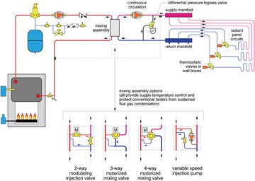
This situation is greatly improved by adding outdoor reset control of the water temperature supplied to the radiant panel circuits. In a system with properly set reset control, the water supplied to the circuits is just warm enough to provide the necessary heat output based on the outdoor temperature. This results in the thermostatic circuit valves remaining open a high percentage of the time. They close only as necessary to prevent overheating from internal heat gains. Think of them as "over-temperature protection devices" rather than "heat initiation devices."Outdoor reset control can be implemented as boiler reset control or as mixing reset control.
Boiler reset control limits the temperature supplied by the boiler by pre-empting the action of the boiler's own high-limit control. The warmer it gets outside, the lower the water temperature at which the burner is turned off.
A potential limitation of boiler reset is how low the water temperature can be reduced without creating flue gas condensation in "conventional boilers" (e.g., those designed to operate above the dewpoint temperature of their exhaust gases. With few exceptions, conventional boilers should not be operated at sustained inlet temperatures less than 130 degrees F. Some boilers, primarily of European origin, can operate safely at somewhat lower inlet temperatures. The lower the acceptable inlet water temperature, the greater the range of outdoor reset control.
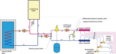
If a condensing boiler is used, low inlet water temperatures are an asset rather than a liability. The lower the boiler water temperature, the greater the rate of flue gas condensation, and the higher the boiler's efficiency. Using a condensing boiler eliminates the need for a mixing assembly. It makes no sense to operate a condensing boiler at a temperature higher than required by the radiant panel circuits and then dilute that temperature through a mixing device.
The piping shown in Figure 5 is suggested when combining a condensing boiler with thermostatic circuit valves. The closely spaced tees allow for situations where boiler flow may be greater than or less than flow in the distribution system. The boiler's internal controller typically provides a full range of reset control. Domestic water heating is provided as a higher temperature priority load using a separate circulator.
Minding Your DPs
As in any system using zone valves, differential pressure across the circulator should be regulated to prevent flow noise or valve lift under low loads when many of the zone valves are partially or fully closed. The classic approach uses a differential pressure bypass valve installed as shown in Figures 3 and 4. The valve's threshold pressure can be set about one psi higher than the differential pressure that exists when all zone circuits are fully open. As zone valves begin closing, and the differential pressure across the circulator rises, an increasing percentage of flow is routed through the bypass valve rather than through the increasingly restrictive thermostatic zone valves.An even better approach to differential pressure regulation uses a variable speed circulator with an integral differential pressure controller. Such a circulator automatically senses the change in differential pressure as thermostatic valve modulate, and instantly adjusts speed as necessary to maintain a constant (user-adjusted) differential pressure. By reducing speed under partial load conditions, they also reduce electrical energy usage. These "smart circulators" are already in use in Europe. It's likely they'll become available in North America in 2005.
Giving A Wake-Up Call: Systems using thermostatic zone valves must have a way to turn on the distribution circulator and fire the boiler when any zone needs heat. Most boiler reset and mixing reset controllers can provide this "heat initiation" action when the outdoor temperature drops below some user-set start-up value (typically 60 to 65 degrees F).
If this functionality is not provided by the reset controller, a setpoint controller that monitors outdoor temperature can be used to enable system operation.
Another approach uses a single electric "master thermostat." The distribution circulator operates and boiler firing is enabled whenever the contacts in the master thermostat are closed. When the master thermostat is satisfied, the boiler and circulator are turned off, and no heated water is delivered to any of the radiant panel circuits.
I've used this approach and found that setting the master thermostat two to three degrees above the normal desired indoor temperature works well. With this setting, the master thermostat keeps the warm water flowing under normal conditions, but stops heat input when internal gains drive the indoor temperature up slightly above the normal comfort setting. Keep in mind that many of the thermostatic zone valves will be closed based on their own room comfort settings before the master thermostat is satisfied.
A master thermostat also allows the owner to put the entire system into a setback mode without having to turn down each of the thermostatic zone valves. As individual rooms cool, their thermostat zone valves open, but no heated water is delivered until the temperature at the master thermostat location drops just below the setback temperature. The master thermostat could even have a programmed setback schedule.

