Some of the folks sending these SOS messages launch into their own speculations on the cause of the problem. It's common to hear reasoning like this: Since the house isn't getting warm enough, the boiler(s) must be too small. Although this seems logical to the average homeowner, inadequate boiler capacity is seldom the cause of inadequate heating.
Here's a question I like to ask right up front: When it's very cold outside, perhaps even the coldest day of the winter, does the boiler run almost all the time?
With few exceptions, the answer is no.
What could you conclude from this response? The likely explanation is simple. The boiler is reaching its high limit and shutting off because it's creating heat faster than the remainder of the system can dissipate that heat. In other words, there's a “bottleneck” in the heat transfer process somewhere between the heat source and the heat emitters.
Hydronic bottlenecks fall into two categories; flow bottlenecks and heat transfer bottlenecks. Both can lead to complaints of inadequate heat output. This month we'll look at what causes some of these bottlenecks and what you can do to avoid them.

Watch Those Cv Values
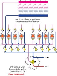
Last year we looked at a system in a large custom home where eight manifold stations, each serving several radiant floor heating circuits, were supplied through a single 3/4-inch thermostatic mixing valve. Figure 1 depicts the situation.The word “bottleneck” hardly does justice to this situation. The 3/4-inch three-way thermostatic mixing valve had a Cv value of 3.0. (The Cv number is the flow rate of water in gallons per minute that produces a 1 psi pressure drop across the valve.) The use of such a valve to serve a single manifold is sometimes questionable due to the valve's relatively limited flow capacity. Multiply that situation by eight and you're now working with trickle rates rather than flow rates.
Needless to say, the home was underheated. The temperature drops across some of the radiant floor circuits were over 50 degrees F. Assuming the radiant tubing circuits have reasonable lengths, such large temperature drops almost always point to inadequate flow.
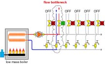
Fortunately, that part of the system was relatively easy to correct. The three-way valve was removed and a variable-speed injection mixing system was installed as shown in Figure 2.
Low Mass + Low Flow = Problems
Another example of a flow bottleneck is when a low-mass boiler is piped to a header full of zone valves, as shown in Figure 3.Low-mass boilers need ample flow whenever they are fired, even when only one zone circuit is active. The piping shown in Figure 3 reduces flow through the boiler as the number of active zones decreases. At some point, boiler flow may be low enough to allow steam flashing inside the boiler's heat exchanger. Low flows also increase thermal stresses on boiler components.
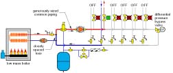
One solution is to pipe low-mass boilers as a secondary circuit as shown in Figure 4. In this approach, the flow through the boiler is constant whenever the boiler circulator is operating, and not dependent on the number of active zone circuits. Another possibility is to install a hydraulic separator between the boiler circuit and distribution system as shown in the January 2005 Hydronics Workshop column (see “Piping For 'Wallies',” January 2005, online at www.PMmag.com in PM's editorial archives).
DHW Asphyxiation
Indirect water heaters used to supply high-demand domestic hot water loads can create both thermal and flow bottlenecks. Flow bottlenecks typically result from undersized piping or an undersized circulator between the boiler plant and the tank's heat exchanger.Here's an example: To transfer heat to the potable water at 150,000 Btu/hr. using a 20-degree F temperature drop across the heat exchanger coil requires a flow rate of about 15.3 gallons per minute. This is much higher than what a 3/4-inch tube can carry at reasonable flow velocities. However, at least one currently available indirect tank with an input rating of 150,000 Btu/hr. comes with 3/4-inch coil connections. It's hardly surprising such tanks usually get piped into the system with 3/4-inch tubing, and a small 1/25 horsepower circulator. After all, surely the tank manufacturer knows what tube size is needed and provides connections of that size.
Given the rate of heat transfer and flow rates we're discussing in this example, I would suggest a minimum tube size of 1.25 inches. The head loss of the DHW coil circuit should then be calculated, and a circulator capable of providing at least 15.3 gpm at this head selected for the DHW heat exchanger circuit.
The heat dissipation ability of the internal heat exchanger in an indirect water heater tank can also create a bottleneck to DHW production. For example, a large 120-gallon indirect water heater may have a coil rating in the range of 250,000 Btu/hr. when supplied with hot 180 - 190 degree F boiler water at a flow rate in the range of 26 gpm. Imagine this tank connected to a multiple boiler system capable of 400,000 Btu/hr. heat output as shown in Figure 5.
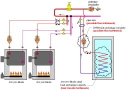
Remember, thermodynamics wants a balance between heat input and heat dissipation and will drive the water temperature up or down to achieve this balance. It won't be long before the boiler staging control shuts off one or both boilers because the water temperature quickly reaches the target value and would likely overshoot if the boilers remained on longer. The staging control doesn't understand there's a bottleneck to heat transfer in the heat exchanger. Even if it did, there's nothing it could do to correct the situation. Obviously, a boiler that's off - even for a few minutes - is not producing heat to help meet a high DHW demand. The tank's heat exchanger, and not boiler capacity, is the bottleneck limiting how fast DHW can be supplied.
One remedy for this situation is to use an external plate-type heat exchanger that's sized to transfer the full output of the boiler plant into the storage tank while operating at reasonable temperatures and flow rates as shown in Figure 6.
Another approach would be to install an additional storage tank and, thus, increase the available heat exchanger area between the boiler water and potable water. This would not be my preferred solution. The two indirect tanks are going to cost at least as much as an external heat exchanger, bronze circulator and standard storage tank. Two tanks certainly require more space in the mechanical room. Most importantly, the second tank significantly adds to tank surface area, which increases standby heat loss. This extra heat loss is likely to be the big expense over the life of the system, especially when you consider how it adds to the building's cooling load in warm weather.
The second law of thermodynamics always favors storing energy in a high-grade form (e.g., fuel) rather than converting it to a lower-grade form (heat) until just before the lower-grade energy is needed. This is the underlying advantage of instantaneous water heaters. The design shown in Figure 6 is a hybrid between a purely instantaneous heater and a storage tank system. It has the “full afterburner” power level to keep up with a high DHW demand when necessary, but also allows for small DHW draws without necessarily operating the boilers.

Thermally Constipated Floors
Another thermal bottleneck worth noting occurs when some types of radiant floor installations can't deliver the necessary heat transfer to maintain a room at normal comfort temperatures. This happens when the “heat transfer geometry” between the tubing and the upper surface of the floor just can't wick heat away from the tubing as fast as the space above loses heat. Under such conditions, the nonnegotiable first law of thermodynamics mandates that room temperature drop to establish a balance between the lower rate of heat release from the floor and the heat loss of the room. The water returns from the floor circuit with minimal temperature drop, indicating much of the heat loaded on at the mechanical room has just made the round trip without jumping off.As you design hydronic systems, especially those expected to handle large loads, keep your eyes open for any bottlenecks that might constrict flow or heat transfer. Be sure the full output of the heat source(s) can reach the intended loads and be released by the heat emitters. In every system, the temperatures and flow rates will settle to values where a balance occurs between energy production and energy dissipation. Be sure you select equipment so this balanced condition also provides the expected comfort levels in the building.
