Just about all of these boilers use sealed combustion, which draws combustion air directly from the outside and vents exhaust gases directly through the exterior wall to which they are mounted. Their compact heat exchangers are constructed of stainless-steel or cast-aluminum alloys that can handle the corrosive effects of condensing flue gases. Nearly all these boilers can also modulate their heat output from full power down to 20 percent to 30 percent of that rating.

Piping Matters
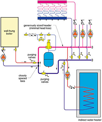
If an installer simply pipes one of these new boilers in the traditional configuration of a cast-iron boiler, he's in for some surprises. The compact heat exchangers used in many of these boilers create much higher flow resistance than does a typical cast-iron boiler block. Trying to push the total flow of several heating zones through this resistance will quickly reveal the boiler as the bottleneck. The flow rate in a given zone will drop as additional zones come on, and flow noise at the boiler is likely.Because of their relatively high flow resistance, these boilers should always have their own dedicated circulator. Figure 1a shows one approach. Install a pair of closely spaced tees (a.k.a. a primary/secondary interface) between the boiler circuit and the remainder of the distribution system. This allows for constant boiler flow, regardless of what's happening with the zone circuits.
An indirect water heater can be piped, as shown in Figure 1a or 1b. With either approach, the system must treat domestic water heating as a priority load. When the domestic hot water load calls, the boiler immediately targets a relatively high setpoint temperature (180 to 200 degrees F). This provides the temperature differential necessary for good heat transfer across the DHW heat exchanger.
An Invisible Fence
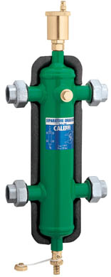
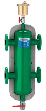
Another piping technique that isolates the pressure differential across the boiler from that in the distribution system uses a "hydraulic separator" as shown in Figures 2 and 3. This device is also called a "low-loss header" by some manufacturers.
This allows several zone circulators to operate at the same time without interfering with boiler flow. The piping schematic is shown in figure 4.

Low flow velocities also allow sediment carried along by the flow to settle to the bottom of the chamber where it can be periodically flushed out through the drain valve.
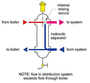
Under such conditions, the fluid temperature supplied to the distribution system is lower than that supplied by the boiler. This is not a problem provided there is proper sensing of the mixed temperature to the distribution system. The sensor measuring this temperature should be installed downstream of the output of the hydraulic separator. Some manufacturers provide a temperature sensor port within the hydraulic separator.
Hydraulic separators for residential and light commercial systems are available in pipe sizes from 1 inch to 4 inches. The size required is based on the maximum flow rate through the unit. The chart shows some suggested piping sizes from one manufacturer.

Mixing Devices Not Required
To achieve the highest possible efficiency, a boiler should be operated at the lowest possible supply temperatures that can "drive" the required rate of heat transfer out of the heat emitters. With conventional boilers, there's a limit to how low the water temperature can be lowered without creating sustained flue gas condensation. A mixing device such as a motorized three-way valve or variable speed injection pump is often used between a conventional boiler and distribution system to allow water temperatures to be fully reset in the latter without damaging the former.In contrast, it makes little sense to operate a condensing boiler at elevated temperatures and use a mixing device to lower the temperature to that required by the distribution system. Doing so would reduce the potential for flue gas condensation and hence lower the boiler's efficiency.
Another important detail with modern wall-hung boilers is to pump into the boiler. This causes the pressure inside the boiler's heat exchanger to increase, which in turn reduces the potential for steam flash or cavitation when the boiler is operating at higher temperatures. Keep in mind that fluid pressure drops and water temperature increases as the flow passes through the heat exchanger. Thus, the greatest potential for steam flash is near the outlet of the boiler. Pumping into the boiler helps keep the temperature/ pressure relationship at this location well above the flash point of the water.
Some wall-hung boilers contain an internal pressure switch to ensure there is adequate pressure within the heat exchanger to prevent steam flash. If the circulator were installed on the outlet of such a boiler, the pressure inside the heat exchanger would drop as the circulator attempts to "suck" water through it. This is a cordial invitation for steam flash as well as some intolerable operating sounds. The pressure switch detects such conditions and turns off the boiler before things get dicey.

Multiple Modulators
One of the slickest boiler solutions now available is a bank of multiple modulating boilers. Such systems provide a high ratio of heat output to space requirement, as well as the safety factor of having partial heat output if one boiler is down.They also provide a very wide system turndown ratio (e.g., the ratio of heat output when all boilers are at maximum power to the output at the minimum stable heat output of a single boiler). For example, a boiler with a peak output of 150,000 Btu/hr. and a minimum stable firing rate of 30,000 Btu/hr. would have a turndown ratio of 150,000/30,000 = 5:1. However, put three of these boilers into one properly controlled system and you achieve a system turndown ratio of 450,000/ 30,000 = 15:1. Another way of looking at this scenario is that the boiler system can reduce its output down to 1/15th (e.g., 6.7 percent) of full power and still maintain good efficiency. Such systems are capable of tracking heating loads very closely and providing just the right amount of heat input.
Multiple modulating boilers should always be piped in parallel as shown in Figure 6. This allows each boiler to receive the lowest possible inlet temperature from the return side of the distribution system. The lower the inlet water temperature, the higher the boiler efficiency.
Each boiler should also have its own circulator and check valve. Flow through a given boiler should only occur when that boiler is firing. This prevents heat generated in one boiler from being partially dissipated by jacket losses in other boilers.
The firing logic used with multiple modulating boilers differs from that used with multiple on/off boilers. When operating for space heating, the goal is to operate the boiler plant at the lowest possible supply water temperature commensurate with the load, and spread that load across as much boiler heat transfer surface area as possible. This operating logic keeps the temperature of the combustion side of the boiler heat exchanger(s) as low as possible for a given firing rate, which promotes condensing mode operation and higher efficiency.
I'm convinced that wall-hung boilers will eventually become the norm in residential and light commercial hydronic systems in North America. Their small size and off-the-floor mounting is a tremendous advantage in tight mechanical rooms. Their sealed combustion systems prevent draft fluctuations due to other exhaust fans in tightly sealed buildings. Add to this their high efficiency, fast thermal response, built-in outdoor reset logic, and whisper-quiet operation and you have a power plant that North American hydronic heating pros only dreamed about 10 years ago.
MEC Seminars Back For 2005
John Siegenthaler's successful one-day Modern Engineering Concepts for Hydronic Heating Design seminars are back in 2005. Attendees will learn about both residential and commercial hydronic heat systems, and how to design efficient, affordable and reliable systems using the latest technology.The registration fee of $395 includes hydronic circuit simulator CD software, design workbook, certificate of course completion, and lunch and beverages.
The first MEC dates and locations are April 14 in Pittsburgh and April 15 in Cleveland. Find an MEC seminar in your area and register today at www.bnpmedia.com/mec-registration.html.
