One of the best known temperature control devices in hydronic radiant heating systems is the three-way thermostatic mixing valve. It's available from several manufacturers with either an internal thermostatic element or an external actuator. The latter uses capillary tube sensing bulbs for temperature measurement.
Because these valves have been around for decades, many installers feel they fully understand how such valves work and how to install them in a radiant heating system. Unfortunately, the number of problem jobs that I see or hear about suggests otherwise.
Let's look at both the right and wrong way to apply these valves.

Where The Circulator Goes
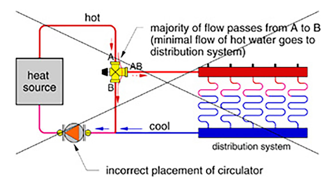
The proper piping of a three-way thermostat valve is shown in Figure 1. Hot water enters port A and mixes with cool return water entering through port B. The resulting mix flows out through port AB and heads for the radiant floor manifold(s).Note that the distribution circulator is located between the mixing valve and the manifold station. With the pump in this position, the proper flow rates can be generated through the distribution system. Unfortunately, the old habit of installing circulators so they pump into the return side of the boiler has resulted in systems such as the one shown in Figure 2.
In such installations, almost all the hot water from the boiler outlet is routed through the internal porting of the mixing valve and back to the boiler inlet. This happens because flow leaving the discharge port of a circulator only "cares about" getting back to the inlet of the circulator. The path of least resistance is through the porting of the mixing valve rather than through the floor circuits. Only a trickle of hot water flows through the latter. The high supply temperature and extremely low flow rate lead to very large temperature drops along the circuit and severely hinders heat output. Any heat that makes it out to the floor circuits is more of a coincidence rather than planned occurrence.
When One Isn't Enough
Another common mistake is to install a single three-way thermostatic valve between a conventional gas- or oil-fired boiler and a low-temperature radiant floor or snowmelting distribution system as shown in Figure 3.Although this piping can regulate the supply water temperature, it offers no protection against flue gas condensation within the boiler. Any cool water returning from the distribution system that doesn't flow into the cool port of the mixing valve goes directly back to the boiler. In low-temperature floor heating systems, the return water temperature is often 85 to 100 degrees F. This is well below the dewpoint of the water vapor in the exhaust gases and causes sustained flue gas condensation whenever the system is operating -- even under design load conditions. This can quickly lead to severe fireside scaling and corrosion. It can also quickly destroy a galvanized vent connector pipe.
One way to solve this problem is to install a second mixing device as shown in Figure 4. This device may be another three-way mixing valve or one of several available "preset" thermostatic mixing devices specifically designed for boiler protection. Some boiler manufacturers even build such thermostatic bypasses into some of their boilers.
The second three-way thermostatic valve bypasses hot water from the boiler outlet back into the return water flow whenever it senses the return temperature falling below its setpoint. This action limits the amount of heat delivered to the other three-way valve when necessary to prevent the distribution system from gulping down heat faster than the boiler can produce it. Unless the boiler manufacturer recommends otherwise, this valve should be set for about 130 degrees F.
If the heat output rating of the boiler is at least four times greater than the design load of the low-temperature distribution subsystem, the second three-way valve may not be needed. An example would be a small radiant slab supplied from a boiler that also supplies the bulk of its heat output to high-temperature baseboard. In such cases, the boiler has the "brute force" to overcome the low-temperature return water sent back to it by the small (but often cool) radiant slab.

Misunderstood Bypass
It's also common to hear the claim that a boiler bypass circulator will boost boiler inlet water temperature high enough to prevent sustained flue gas condensation. This is not always true.A bypass pump does provide a second mixing point to boost the boiler inlet temperature when the rate of heat production exceeds the rate of heat release. It also helps protect the boiler from thermal shock, and maintains an adequate flow through the boiler under low load conditions in systems with several zone valves. These are all beneficial functions.
However, during a cool slab start-up, or during a recovery from a deep setback, the slab can extract heat from the water flowing though it up to four times faster than during design load conditions. Under such conditions, a bypass circulator cannot make up for the energy deficit. It will only stir the contents of the boiler as its temperature steadily drops.

The Magic Of Closely Spaced Tees
I also see a number of piping designs where the pressure drop created in other parts of the system under various operating modes interferes with the modulation of the three-way valves. This can be solved by connecting the three-way valve and the distribution system it serves to the boiler loop using a pair of closely spaced tees as shown in Figure 4.With this primary/secondary interface, flow through the three-way thermostatic valve is driven solely by the pressure differentials created by the radiant distribution circulator. The operation of other circulators in the system will not interfere with these flow proportions. It's just another example of how coupling loops together using closely spaced tees (e.g., primary/secondary piping) helps keep the peace among several circulators. This piping is also appropriate when motorized three-way valves are piped into a system.
Use the piping techniques we've discussed to make the three-way valves you install work as you intended. They'll return the favor by providing years of accurate and trouble-free service.

