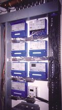
- Boiler reset controller.
- Boiler staging controller.
- Injection mixing controller.
- Zoning controller.
Figure 1 shows an example of a mechanical room with a healthy share of stand-alone controllers that have been merged into such a system.
A system of such complexity usually requires hours to install and “tweak” into smooth operation. Over the years, many of us have spent hours in the truck getting to some remote jobsite to make these adjustments. On the drive home, we've wondered if another trip will be necessary because all the dials and switches are not in just the right position. Needless to say, there is room for improvement.
Let's Talk
New methods for system control hold the potential to greatly reduce installation and final adjustment procedures.A new generation of communicating control products is currently establishing itself in the residential and light commercial sector of the hydronics industry. These new products allow technicians to monitor and adjust the system operation from a remote location using one or more types of digital communication.
This is probably no surprise to those who have worked with larger commercial or institutional HVAC systems in the last few years. Building automation systems (BAS) now allow the authorized personnel to view and adjust hundreds of system-operating parameters from a PC either on- or off-site. In many cases, these systems control lighting, fire protection, elevators and security functions as well as the HVAC system.
Advances in digital technology including microprocessor capability, size, power requirements and onboard memory have made it possible - both technically and economically - to scale BAS concepts down for smaller systems.
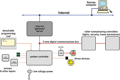
Communication between controllers, sensors and controlled devices is the key difference between the past and future of HVAC controls. The concept of communicating control devices is shown in Figure 2.
The red horizontal line represents a digital communications “bus.” It typically consists of a two-wire pair running between the various devices. The communications bus transmits very low power digital signals, and does not power the devices on the network. Operating power such as line voltage for circulators or 24 VAC for motorized valves is still necessary.
Each device on the network has a unique digital address (e.g., a specific binary “call sign”). Any given device can only send or receive information when its address is active on the communications bus. At other times the encoded instructions flow past that device without invoking any action. Collectively, all devices connected to the bus form a network (or as it's sometimes called, a LAN - local area network).
The speeds at which digital information flows across the communications bus makes it possible for any given device on the network to send or receive information hundreds, if not thousands, of times each second. Given the response characteristics of most HVAC systems, this is more than adequate, even when hundreds of devices share the same bus.
Every device on such a network must be a “smart device.” It must have the embedded hardware and software necessary to listen and speak to the other devices. The physical location of a given device on the network is usually irrelevant; it's the digital address that counts. When a new device is attached to the network, the system controller automatically detects it and assigns it the necessary address for communications. It's akin to how we can now “hot swap” USB or FireWire™ peripherals on modern computer systems.
Full implementation of this concept requires devices such as motorized valves, circulators and heat sources with equipment for network communication. Such smart devices already are on the market if you know where to look, and more are headed your way in the very near future.

Beam Me Up
Besides communication between smart devices on the same LAN, some systems can be equipped with a “gateway” allowing communication over the Internet.The gateway provides a unique URL address number (such as 12.345.6.78) that can be typed into any Web browser, such as Internet Explorer® or Firefox®, to initiate the login process.
A username and password are required to login. Some users and passwords are restricted in their capability to access or change controller operation.
Once the login is completed, a unique Web page is displayed along with available options:
- Systems on the network (HVAC, lighting, security).
- Zone information.
- Operating schedules.
- Alarms.
- Graphs or charts from previous data-logging routines.
An example of how such data can be read from a remote computer screen is shown in Figure 3. Figure 4 demonstrates some of the data-logging capabilities of such a control system.

One's Enough
A very important advantage of communicating control devices is the elimination of redundant components such as:- Power supplies.
- Transformers.
- Displays.
- Keypads.
- Sensors.
In a networked system, a single outdoor sensor can supply the outdoor temperature information to every device that requires it. This is not only possible, it's on the market right now waiting to save you time, cost and lower the probability of malfunctions over time. A communicating control network is also far less prone to control conflicts that can arise when each of several noncommunicating controllers is individually set.
Ready Or Not, Here They Come: In the years ahead, communicating control networks will become the standard in residential hydronic systems. Most will have the ability to be accessed through the Internet. It's also a sure bet that such control networks will talk to devices on the air-side of overall HVAC systems as well as other appliances within a typical home.
Comfort professionals who expect to remain current and competitive in this quickly evolving market should begin “tooling up” on the technology. One reference that I think provides a great generic introduction to these concepts is a book titled “The Fundamentals of HVAC Direct Digital Control, Practical Applications and Design, Second Edition,” by Frank Shadpour, P.E.
