
When such situations occur, the first law of thermodynamics dictates that the system's water temperature must drop. Nature always strives for a balance between heat production and heat dissipation. The system's water temperature will always attempt to rise or drop to maintain this balance. Only the intervention of controls or safety devices can intercede to prevent the system from reaching temperature (high or low) based on maintaining this energy balance.
In past columns we've discussed the need for boiler inlet temperature protection when a conventional boiler (e.g., one not intended to operate with sustained flue gas condensation) is matched up with a high thermal mass load. The bottom line is that proper boiler protection in such situations requires a “thermal clutch” between the boiler and distribution system. This clutch must be capable of sensing a low inlet temperature to the boiler and react by limiting the rate of heat transfer to no more than the rate of heat output by the boiler.
Some hydronic system designers have long been under the impression that a fixed boiler bypass arrangement, such as shown in Figure 1, provides all the protection a boiler needs.

When the load's ability to extract heat from the water exceeds the boiler's heat output, a fixed bypass piping configuration cannot prevent a drop in system water temperature. To do so would require it to sidestep the first law of thermodynamics - and that just ain't gonna happen.
Depending on the operating temperature of the load, its thermal mass, and the boiler capacity, it's entirely possible that the boiler with fixed bypass piping will operate in a flue gas condensing mode for extended periods. The result is scaling, corrosion and premature failure of an otherwise fine boiler, vent connector, and possibly even serious damage to the chimney.
An Intelligent Approach: The underlying problem with a fixed boiler bypass is that it lacks the intelligence needed to adapt to changing load conditions. Without such intelligence, it cannot function as a thermal clutch between the boiler and load.
Fortunately, some newly released products are providing a way to add brains to bypasses. These new devices are known as setpoint-controlled variable speed circulators. They combine the mechanical components of a standard wet rotor circulator with the modern electronics necessary for variable speed control. A couple examples are shown in Figure 2.
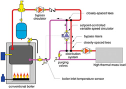
The operating logic is straightforward. The controller built into the circulator monitors a single temperature sensor and compares the measured temperature to a previously set target value. When configured in the “reverse acting” mode, the speed of the circulator decreases as the temperature measured by the sensor decreases. Decreasing the circulator speed reduces the rate of heat transfer from the boiler loop to the distribution loop.
Many of you probably are thinking this is just an injection pump setup. True, the piping looks virtually identical. Keep in mind, however, that the circulator is not monitoring or controlling the supply water temperature to the load. Its sole function is to protect a conventional boiler by preventing the load from extracting heat faster than the boiler(s) can produce it. Supply temperature would have to be controlled by another device.
Another important difference between this application and injection mixing is that there may not be any mixing at the closely spaced tees connecting the bypass risers to the distribution system. The setpoint-controlled variable speed pump should be sized to transfer the full heat output of the boiler using the design temperature drop of the distribution system. This temperature drop will usually be considerably less than the temperature difference between injection mixing risers when a conventional boiler supplies a low-temperature load. Thus, the size of the bypass risers will be larger, in most cases the same size as the distribution mains.
Keep in mind that the head loss the setpoint-controlled variable speed circulator “sees” in this arrangement is only that of the bypass risers, which will typically be quite low. Thus, a circulator with a high flow/low head characteristic is called for.
In Figure 3, the variable speed circulator is shown on the return riser rather than the supply riser. Placement within either riser is possible with no difference in performance. However, putting the circulator on the return riser allows it to operate at slightly lower water temperatures.
Boiler Lifeguard
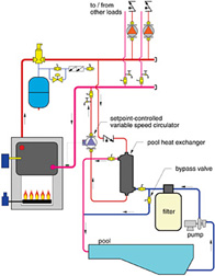
A great application for a smart bypass is where a swimming pool is being heated by a conventional boiler through a heat exchanger. The piping is illustrated in Figure 4.The setpoint-controlled variable speed circulator acts as a metering device between the boiler and pool heat exchanger. It constantly monitors the boiler inlet temperature, and slows down when necessary to prevent the heat exchanger from extracting heat faster than the boiler could produce it. This is especially important if the heat exchanger is oversized and thus capable of pulling the boiler down into condensing mode using the enormous thermal mass of a cool swimming pool.

Heat Pump Helper
Another excellent application for a setpoint-controlled variable speed circulator is to protect the boilers in a commercial water source heat pump system. Such systems continuously circulate water around a building piping loop that connects to several independently operated water source heat pumps. Each heat pump can operate in either heating or cooling mode depending on the needs of the space it serves. Those operating in the heating mode extract heat from the building loop, while those operating in cool mode dump heat into the loop.In winter, there are times when the rate of heat extraction by heat pumps in the heating mode exceeds the rate of heat dissipation into the building loop by the few heat pumps operating in cooling mode. Under such conditions, the temperature of the building loop drops. When it gets down to a nominal 70 degrees F, one or more boilers are fired to add heat to the loop.
This situation can be a real “boiler killer” if the interface is not done properly. I have seen this firsthand on two jobs. In both jobs, the boilers were toast inside of 10 years. One job used copper tube boilers, the other used cast-iron sectional boilers. The underlying problem in both was inadequate or nonexistent boiler temperature protection.
By interfacing the boiler to the building piping loop as shown in Figure 5, a set-point controlled variable speed circulator can provide the thermal clutch between the boiler(s) and building loop. Again, this pump's sole purpose is to protect the boilers and not to control supply temperature in the building loop. The latter is done by the controls associated with the heat pump system.
At boiler start up, the variable speed circulator would remain off or at a very low speed and thus not allow heat to flow from the boiler plant to the building loop. This allows the boiler inlet temperature to climb rapidly. As it approaches the set minimum temperature, the variable speed circulator slowly ramps up its speed to transfer heat to the building loop.
The cost of installing such a device is far less than replacing one or more boilers sent to an early grave by an ineffective fixed boiler bypass arrangement. Indeed, their use may even cost less than the hardware involved in a typical fixed bypass piping arrangement. Feel free to bring this up to your local consulting engineer when the opportunity arises.
Turns out that boiler protection is only one of several uses for these new setpoint-controlled variable speed circulators. We'll discuss some more applications in future columns. In the meantime, keep your eyes open for new, small variable speed circulators from North American manufacturers. Their time has come, so get ready to use them.
Siegenthaler Seminar This July
John will be discussing "thermal clutches" as well as other innovative hydronic system design techniques in a full day seminar entitled Modern Engineering Concepts for Hydronic Heating Design. These seminars will be offered at six locations in the US. You can get full information on the seminars as well as register online at www.bnpmedia.com/events.htm#mec
Siegenthaler at ISH North America
John Siegenthaler, P.E., is a scheduled speaker at this year's ISH North America trade show held Oct. 14-16 in Boston. He will present a radiant discussion on multiload systems Thursday, Oct. 14 at 9 a.m., and Friday, Oct. 15 at 3 p.m. To register for the show, visit www.ish-na.com.
