In many two-story homes, radiant floor heating is selected for the first-floor living areas, while the second floor is often equipped with baseboard, panel radiators, or a mixture of the two. A common request is to have floor heating in the bathroom(s) of the second floor, while using baseboard in the bedroom areas to reduce installation cost. Many folks opt for nice cushy carpets in those bedrooms which often rules out floor heating. Certainly this hybrid approach is possible, and can be technically executed in several different ways. This month we'll discuss a relatively simple approach that delivers exactly what these folks are looking for.
Bathroom Bliss
Modern bathrooms are marketed as an "oasis of comfort." The lavishness of the bathroom fixtures now installed in otherwise ordinary homes affirms that many consumers are willing to spend beyond the minimums when it comes to creating their own oasis of comfort. Hydronic heating professionals should be ready with solutions to the thermal side of this picture.One amenity that's hard to resist is a warm, dry towel waiting at the end of a shower, bath or, for those high-end projects, a tropical downpour hydro-massage experience. Now take it one step further. As your customers wrap warm, dry towels around themselves, their feet enjoy the toasty-warm ceramic tiles. The floor feels like a walk on the beach at sunset instead of a misstep into a pothole full of slush.
Time and again those customers are reminded what a smart decision it was to include both towel warmer and floor heating in their oasis of comfort. Chances are their guests will also come away with the same impression. The bottom line: This kind of installation is a built-in place, no-cost, perpetual advertising machine that's sure to bring you referrals.
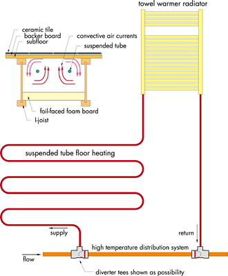
One approach to providing both warm towels and warm floors is shown schematically in Figure 1. It combines a "suspended tube" floor heating system with a towel warmer in a simple series circuit.
The suspended tube system is used because it operates with relatively high water temperatures in the range of 160-190 degrees F. This allows the possibility of tying to the distribution system supplying the baseboard without a mixing device. Besides lowering cost, doing away with the mixing device eliminates the need for an additional circulator between that mixing device and the floor circuit(s). Flow through the floor circuit/towel warmer can be powered by a flow restrictor valve between a pair of tees, or in some cases by a pair of diverter tees. In a system where hot water is always available, flow through the circuit could also be regulated by a thermostatic radiator valve installed on the panel radiator.
The suspended tube system diffuses the heat across the underside of the floor better than does a direct-contact, staple-up approach. Convective air currents within the joist cavity bathe the underside of the floor in warm air. The heat conducts upward through the subfloor, underlayment and tile to deliver the comfort only radiant heating can to the occupants above.
One approach would use bare tubing at 8-inch spacing (assuming typical 16-inch o.c. or 24-inch o.c. framing). The tubing would be loosely supported by clips fastened to the underside of the subfloor, or by light gauge duct hangers that span between joists. Another option would be to run the tubing perpendicular to the joists and install convection-enhancing perforated aluminum fins on the tubing. The perforated fins effectively extend the surface area of the tubing, allowing greater heat outputs relative to bare tubes operating at the same water temperature. Several tubing manufacturers publish thermal performance data on bare suspended tubing. At least one manufacturer publishes thermal performance data on the extended surface area finned tubing approach.
My tubing preference in both these approaches is PEX-AL-PEX. The aluminum core adds structural stiffness to minimize any sag when the tubing is operating at high water temperatures. The lower coefficient of thermal expansion also minimizes the potential for expansion/contraction sounds when the system is subject to rapid changes in water temperature.
Figure 1 shows the radiant floor circuit upstream of the towel warmer. This approach slightly increases the output of the floor as a percentage of total output. It also operates the towel warmer slightly low in temperature for situations where small children or otherwise tender skin may contact it. The flow direction could certainly be reversed depending on the tubing installation method used in the floor, and/or the size of the towel warmer.
Still another floor heating option is to install a single length of finned-tube element (such as that used in baseboard) in each joist bay. Over the years, I've heard several descriptions of successful installations using this technique. However, at present I do not have data that correlates heat output to water temperature, element placement within the joist cavity, underside insulation, and so forth. I remain on the trail of this information, and once located and suitably digested, will report it to you in a future column.

Give Me Independence
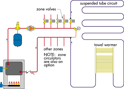
Although relatively simple, the piping shown in Figure 1 "slaves" bathroom heating to the distribution system supplying the other rooms. The bathroom is heated only when this distribution system is operating. This may or may not be acceptable to the occupants. If they're like many of my customers, they'll prefer to keep the bedrooms cool, but wake up to a cozy, warm bathroom. Fortunately, the versatility of hydronic heating technology lets you respond to such a question with, "Yes, we can do that."Figure 2 shows a simple piping option that allows the bathroom to be a separate zone. Again, selecting a high-temperature floor heating method eliminates the need of a mixing device. The zone is controlled like any other baseboard zone with its own circulator or zone valve.
Details, Details
As with any floor heating system, be sure to install good underside insulation. If I-joist floor framing is used, a 2-inch layer of foil-faced polyisocyanurate foam board cut so it lays on the lower flanges of the I-joists is a simple way to provide a nominal R-13 rating. Some of the foil/bubble pack insulation products now available are also well-suited to this type of installation.Also be sure that heated joist bays are sealed off from both adjacent floor areas, and especially from air leakage and conduction losses at the band joint. Spray-applied foam insulation is hard to beat for sealing/insulating the latter.
Whenever possible, I suggest routing electrical wiring, cold water piping and drainage piping around the heated joist bays. Although the air temperature in the joist bays is unlikely to exceed 120 degrees F, the cooler electrical wiring, the safer it remains. Ditto for cold water piping. The main concern for drainage piping is evaporation of water from traps over extended periods. If it is not possible to locate the trap away from the heated joist space, it should be wrapped in insulation. The floor area directly below closet flanges should also be insulated to avoid softening the wax ring.
From the standpoint of head loss, a typical parallel-tube towel warmer radiator offers very little flow resistance. Nearly all the head loss comes from the floor circuit. Figure 3 plots head loss curves for 1/2-inch PEX-AL-PEX circuits of various lengths. Use this graph to estimate the head loss of the circuit plus any leader length of tubing back to a manifold, or other point of attachment to the distribution system.
The formula used to generate this plot is:
HL = 0.038 x L x f1.75
Where:
HL = head loss of circuit (in feet)
L = length of 1/2-inch PEX-AL-PEX tube circuit (in feet)
f = flow rate (in gpm)
For example: What is the head loss of 125 feet of 1/2-inch PEX-AL-PEX operating at a water flow rate of 0.9 gpm?
Just plug in the numbers. Remember the 1.75 is an exponent, not a multiplier. You'll need a scientific calculator or spreadsheet to make this calculation.
HL = 0.038 x 125 x 0.91.75
The plot and formula are based on water at an average temperature of 160 degrees F. Higher water temperatures would result in slightly less head loss.
If the tubing is installed at 8-inch centers, approximately 1.5 feet of tubing will be required for each square foot of floor area. Remember to account for this when estimating the circuit length and its head loss.
There you have it. A simple yet elegant way to keep towels toasty, toes tepid and testimonials talking. Think about how you might use it in one of your upcoming projects.

