
Figure 1

Figure 2
Power Supplies
There are two different types of power supply: line voltage (usually 120V) and low voltage (24V). Boilers, furnaces and air conditioners run on line voltage. Their controls usually run on low voltage. There's a different symbol for each type. Figure 2 is the symbol for a line voltage power supply. It's easiest to just accept this as the symbol for where line voltage comes from, and let it go at that. But many of us want to know a little more. So here's what this symbol is about. There are two arrows pointing in the same direction. What are they pointing to? Intuitively, we want them to point a direction for the electricity to go. But if you try to make sense out of that idea, it just doesn't work. I've asked many engineers and no one knows for sure why that symbol is the way it is. My electrical engineer buddy, Mike, said he never thought about it - that's just the way it is. But when pressed about what it might be, he said he thinks the arrows represent the male side of a connection. They're like the plug on the end of the toaster cord; they show where the circuit plugs in. But plug into what? Before I got Mike's conjecture, I made up my own explanation. It works, too. Those two arrows are pointing to where the electricity comes from - the power plant. In real life, the connection is simply going to be to where electricity enters the building. Sometimes, but not always, the two lines from the arrows have “L1” written on one, and “L2” on the other. L1 is the “hot side” or “hot leg.” L2 is “neutral.”
Figure 3
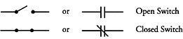
Figure 4
Switch
The second symbol found in a circuit is a switch. Figure 4 shows symbols for a switch. A switch may be shown either “open” or “closed.” Open is just like a drawbridge. That means it's off, because there's no path for the electricity to go on.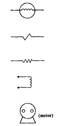
Figure 5
Load
A load is the third and final part of a circuit. A load makes it difficult for the electricity to pass through. Thus the symbol for a load usually is some sort of squiggle, symbolizing that there is resistance to the electricity's passing through. This resistance, of course, is what changes electricity into another form of energy, such as heat, light, motion, sound or magnetism. Figure 5 shows symbols for loads. When the load is a motor, you just have to imagine the squiggle inside it. When we put the three symbols together with lines, we have a complete circuit.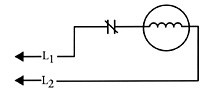
Figure 6
Figure 7
Fey at ISH North America
Carol Fey is a scheduled speaker at this year's ISH North America trade show held Oct. 14-16 in Boston. She will present “The Fun & Effective Way To Teach Controls Wiring To Your Employees” Thursday, Oct. 14 at 3 p.m. and repeat the session Friday, Oct. 15 at 9:45 a.m. To register for the show, visit www.ish-na.com.