All physical systems, whether mechanical, electrical or thermal, need some type of stabilizing effect to prevent rapid fluctuations in their output.
A flywheel provides this stabilizing effect for an engine. The rotational inertia it adds prevents the engine from abruptly jerking to a halt when there's a sudden but brief increase in its loading.
In electrical systems, capacitors stabilize voltage by temporarily absorbing the energy during voltage spikes and then releasing this energy to minimize voltage droops.
In heating systems, the stabilizing effect is called thermal mass. Every component that changes temperature as the system operates contributes to its thermal mass. Cast-iron and steel boilers often constitute a large percentage of the thermal mass in traditional hydronic baseboard systems. When properly utilized, this thermal mass can reduce emissions, improve control response, decrease wear on system components and even improve fuel efficiency. When ignored, the system operates more like a shallow-breathing distance runner. Both may finish the course, but neither will set any performance records.

Heat Held Hostage
Imagine a typical 100,000 Btu/hr. hydronic baseboard system. Let's say it contains a total of 200 feet of baseboard, 150 feet of interconnecting 3/4-inch copper tubing and a single cast-iron or steel boiler.Now ask yourself these questions: What percentage of the system's total thermal mass do you think is contained in the boiler? How much heat is left in the boiler when it shuts off full of hot water?
To answer these, I looked up the specs on some representative cast-iron and steel boilers, as well as piping, and then made a few calculations. They're summarized in Figure 1.
The bottom row in the table shows how much heat would be released from the boiler's thermal mass if the wetted metal and internal water volume were cooled 60 degrees F during the off portion of each burner cycle. Both boilers contain a considerable amount of heat when shut off full of hot water - heat that could be used elsewhere in the system rather than simply waiting for air currents to carry it up the chimney.
What follows are several techniques for exercising the thermal mass of the boiler. Some discuss the advantages of moving residual heat out of a boiler during the off-cycle. Others describe how control stability can be improved by keeping the boiler's thermal mass online while the load is active. All involve the concept of deep cycling the boiler's thermal mass when appropriate.
What You Set Vs. What You Get
Using a limit control with a wide differential will lengthen the boiler's coasting time between burner cycles. The wider the differential, the more the boiler's thermal mass is exercised.Most standard-limit controls have factory set, nonadjustable differentials of 8 degrees F to 10 degrees F. These numbers were established to minimize variations from supply water temperature to heat emitters.
Interestingly, many of us have watched the water temperature in boilers equipped with these controls vary by as much as 40 degrees F between burner-on and burner-off conditions. These wider-than-expected operating differentials usually are caused by poor thermal coupling between the control's sensor bulb and the boiler water. The lack of thermal grease on the sensor bulb, or a sensor bulb that doesn't extend all the way into its well, causes a time delay between when the boiler water attains a given temperature and when the sensor bulb feels that temperature. This results in the water being heated to temperatures well above the limit control's dial setting before the burner is turned off.
Although most standard limit controls are not intended to operate with such a wide differential, there's little doubt such an operation lengthens the burner's on-cycle and off-cycle. This in turn leads to better cycle efficiency and lower emissions per unit of fuel consumed.
Admittedly, a setpoint control with an adjustable differential and fast responding, thermally-coupled sensor is a more predictable method of achieving this benefit. Such a control could allow the burner to turn off at, say, 190 degrees F and remain off while the boiler's thermal mass cooled to, say, 130 degrees F.
Keep in mind a couple of drawbacks come with using wide boiler operating differentials when the heat emitter circuits are piped directly to a boiler.
- The wider the operating differential, the lower the average water temperature and hence, the heat emitters need to be larger. To assure proper output, the heat emitters should be sized for the average water temperature available during the cycle.
- Since piping and heat emitters undergo more frequent temperature changes, it's critical they're installed so that expansion noises will not occur. Although this is always a recommended practice, it's especially relevant in this situation.
One of the best applications for a wide boiler-operating differential is when a modulating mixing device is used between the boiler and the heat emitters. The mixing device continually adjusts to the varying inlet temperatures to maintain a stable outlet temperature to the heat emitters. The boiler'stemperature cycling range needs to remain above the required supply temperature to the heat emitters.

Stop Jerking Me Around
Figure 2 shows a standard setup for a floor heating system using a variable speed injection pump to control the water temperature supplied to floor heating circuits.In such systems, the boiler circulator often is wired to the (C1, C2) terminals of the boiler limit control. When the injection control calls for heat, its contacts complete the circuit through the (T T) terminals on the boiler limit control. This in turn starts the boiler circulator and enables burner firing.
When the injection control decides the water temperature in the boiler loop is warm enough, it opens the circuit to the (T T) terminals, shutting off both the burner and the boiler loop circulator. This can happen even when the injection pump still is running at part-load speed. With no flow in the boiler loop, cool return water coming up the return injection riser does a U-turn at the closely-spaced tees and gets pushed back into the tee at point C. The supply sensor "sees" a rapid drop in the mixed water temperature and respond by ramping up the speed of the injection pump.
When the pump speed reaches a specific speed (10 percent speed on some controls, 50 percent on others), the boiler circulator comes back on. Hot water races out through the boiler loop and heads for the injection pump, which pushes it back into the tee at point C. Now the supply sensor feels a rapid increase in temperature and responds by slowing the injection pump. This "hunting" scenario may repeat itself several times, depending on the temperatures in the boiler and the return side of the distribution circuits. Eventually the stabilizing algorithms in the injection control should dampen out the wide fluctuations.
Now think about how this system would respond differently if the boiler pump stayed on as long as there was a call for space heating. When the injection control shut off the burner, the thermal mass of the hot boiler now would remain online, able to deliver heat to the water circulating in the boiler loop. This would prevent rapid changes in the hot water supplied to the injection mixing system. As the water temperature in the boiler loop slowly decreases, the injection pump smoothly ramps up speed and eventually refires the boiler.
In this scenario, the thermal mass of the boiler and boiler loop water have been exercised to reduce boiler cycling. Wear on the ignition system and other moving parts also has been reduced. Furthermore, this approach improves the boiler's seasonal efficiency and provides a gentler set of conditions for the injection controller to react to. Only after the heating load is satisfied is the boiler circulator turned off.
There are several ways to keep the boiler circulator running whenever there's a call for heat, depending on the mixing control being used. One is to wire a relay parallel to the heat-demand terminals on the injection control (Note: This relay may not be necessary on some controls.) If a relay is used, be sure its coil voltage matches that of the heat-demand terminals on the injection control. Route line voltage to the boiler circulator through the normally-open contact of this relay. When the room thermostat calls for heat, the boiler circulator, but not necessarily the burner, will turn on. The boiler contact in the injection control will operate only the burner instead of the burner and boiler circulator, as in the previous case. Be sure to set the boiler's limit control high enough so as not to interfere with the boiler-operating logic of the injection control. For most systems, 200 degrees F should be adequate.
In cases where the injection control doesn't operate the distribution pump continuously, it's also possible to wire the boiler circulator parallel to the distribution pump. Be sure the combined amp draw of the two pumps does not exceed the amperage rating of the circulator relay in the injection control.
All Warmed Up & No Place To Go
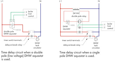
Many of you probably have watched a typical indirect-fired DHW zone go through its paces. When the tank reaches its setpoint, the boiler and DHW circulator immediately are turned off. Lots of heat is left stranded in the boiler, especially when space heating loads are low. Eventually, this heat finds its way up the chimney or out through the jacket insulation. If the tank circulator could just remain on for a few minutes after the aquastat is satisfied, some of this heat could be transferred to the tank instead of wafting away.Figure 3 shows a simple way to keep the DHW circulator operating for a few minutes after the tank aquastat has been satisfied. A delay-on-break time delay relay does the trick. Wire one of the aquastat contacts to the input switch terminals of the time delay relay. Wire the other set to the (T T) terminals on the boiler limit control. If the aquastat doesn't have double pole contacts, you'll need to wire in a double pole relay as shown in the figure to establish two independent, but simultaneously operated, circuits controlled by the aquastat.
Here's how it works: The contacts in the time delay relay close immediately upon a call for heat from the aquastat. This turns on the tank circulator. The timing circuit is "armed" at this point but doesn't start counting until the aquastat reopens. When the aquastat is satisfied, the boiler immediately is turned off, but the circulator remains on for interval set on the relay.
Keep in mind that the DHW tank will get hotter than otherwise allowed by its aquastat. For this reason, it's essential to install an anti-scald three-way mixing valve between the tank and the fixtures it serves.
Stage Exercises
One final method of "deep cycling" the thermal mass of a boiler's typical baseboard system is by using a two-stage thermostat. The first stage turns on the distribution circulator only. Warm water in the boiler is conveyed to the distribution circuit without a simultaneous call for burner operation. If the load is small, the residual heat in the boiler may be all that's necessary to satisfy it. If not, the room eventually cools a couple of degrees and the second stage contacts close to fire the burner.In multi-zone systems, the first stage contacts can operate individual zone circulators or valves while the second stage contacts are wired parallel to operate the burner relay.
As a side note, I'm sure many of you will recall hearing about this two-stage thermostat application from "Gentleman Jim" Roche of the Burnham Corp. Jim is retiring in the near future after 30-plus years of teaching many of us, myself included, the finer points of hydronic heating. Jim, on behalf of all your former students, thanks for your many contributions to our industry, and all the best in the years ahead.
When you buy a cast-iron or steel boiler, you're paying for its thermal mass. In all likelihood, you've occasionally strained to get that thermal mass into some less-than-inviting mechanical rooms. Not using that mass to improve system performance is like ordering a pickup with an optional 50-gallon gas tank and stopping every 50 miles to fill it up.
As you design systems, think about the following key concepts and integrate them where appropriate:
1. Keep the thermal mass "online" whenever a load is operating to lengthen the burner on and off cycles. Fewer but longer burner cycles always are better than frequent but short cycles.
2. Use the widest practical differentials between burner-on and burner-off thresholds to deep cycle the boiler's thermal mass on each cycle.
3. Purge the residual heat parked in a boiler to a load or well-insulated storage tank when it would otherwise be pulled up the chimney or overheat the mechanical room.
