By my count there are at least eight companies now offering panel radiators to hydronic heating professionals in the United States. They range from compact towel warmers to customized units that can be built to follow curved or angled walls. Most manufacturers offer dozens of sizes, shapes and colors. Some models protrude less than 2 inches from the wall they mount to. Others can squeeze into the narrow wall spaces often present in kitchens and bathrooms - places where baseboard is out of the question. Some panels can be "accessorized" with towel bars, mirrors, garment knobs and boot racks. Some European vendors will even scan your favorite photograph or artwork and transfer the enlarged image to a panel. Considering all the options available, they truly deserve to be called "designer" radiators.
Premium heat emitters deserve efficient and effective piping systems. This month we'll look at several options. Creating distribution systems that allow precise individual room temperature control may be easier and less expensive than you think.
Simple Series
One way of piping several panel radiators together is a series circuit similar to the ones that are often used for baseboard. Although arguably the easiest to install, series circuits do have their limitations. Chief among them is the lack of heat output control from each panel.Series circuits should be limited to areas that can be controlled as a single zone. Avoid series circuits if one or more of the panels is located in a room with high internal heat gains relative to the other rooms. You can change the water temperature and you can change the flow rate, but the change always affects the entire series circuit rather than an individual panel. Attempting precise temperature control of several rooms with such a circuit is like target shooting with a shotgun.
Another potential limitation of series circuits is excessive head loss. The individual head losses of each panel and interconnecting piping add together in a series circuit. Too many panels in series will lead to high head loss and low flow rates. The result will be cool panels near the end of the circuit.
Series circuits containing several heat emitters must also be designed to accommodate the drop in water temperature from one heat emitter to the next. In some cases, the size of downstream panels may have to be increased to compensate for the lower water temperatures.
All things considered, I feel the limitations imposed by series circuits usually outweigh their simple-to-install demeanor.
Diversionary Piping
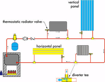
Another panel piping option is a diverter tee system. This approach is well suited for systems in which individual panel radiators will be zoned using thermostatic radiator valves (TRVs) , or electrically operated zone valves.A schematic of the diverter tee piping is shown in Figure 1. The diverter tee is typically mounted as the return tee, which reconnects the branch circuit to the main. Its internal venturi creates the pressure differential that pulls water through the panel radiator when the branch control valve is open. As the room attains its set temperature the TRV slowly closes off flow through the panel.
If TRVs are used to control individual panels, the loop circulator must operate whenever any panel needs heat. One way to do this is to set up a "master thermostat" for the building area served by the circuit. Wire this thermostat to turn on the pump. Keep in mind that the master thermostat can turn off the flow, and hence the heat, to all the panels on the circuit.
For this reason I've recommended it be set two or three degrees above normal room temperature. Locate the master thermostat so that the circulator can be temporarily turned off if the space becomes overheated by internal heat gains.
Another option is to use a setpoint control to tie circulator start up and boiler firing to outdoor temperature. Most boiler reset controls provide both actions, as well as evenly distributing heat delivery by lowering the temperature of the distribution system under part load conditions.
With either strategy, it's important to insulate the distribution piping. With nearly continuous circulation during the heating season, an uninsulated piping loop can ooze a lot of heat. Remember, the idea is to deliver heat in a controlled manner through the panels rather than through uncontrolled losses from the distribution piping. All it will take is a few cold (but sunny) days to convince the skeptic that pipe insulation is a must with this type of distribution system.
Diverter tee systems also create a temperature drop from one panel to the next, which should be considered during design. The circuit could be designed for a customary temperature drop of 15 degrees F to 20 degrees F at design load with all panels operating. It could also be designed for a deep temperature drop of 30 degrees F to 40 degrees F. In the latter case, a small zone circulator will likely be able to handle a good-size circuit. However, the panels near the end of the circuit will probably have to be significantly larger to accommodate the lower water temperatures.
If The Piping Fits . . .
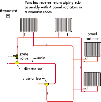
Several years ago I designed a panel radiator system for a large colonial house using the diverter tee approach described above. The living room had four large windows. Aesthetically, it made sense to share the load among four identical panel radiators, one under each of these windows. But how should those four panels be piped back into the system? If connected in series, the pressure differential developed by two diverter tees (one on supply, the other on return) might not be high enough to achieve the proper flow rate. Also, the first panel in the series string would run warmer than the second, and so forth.The solution was to interconnect the panels using parallel reverse-return piping, and then connect that subassembly into the main one-pipe loop using two diverter tees. The concept is shown in Figure 2. The parallel piping ensured each panel got the same supply water temperature and approximately the same flow rate. The overall pressure drop of the parallel piping assembly was also significantly lower than if the four panels had been piped in series. Once again, the versatility of hydronic piping provided a solution.
Another system that's offered by at least one panel radiator supplier is an integral bypass valve. This valve, which resembles an "H", is mounted between the connections at the bottom of the panel and the tubing supplying the panel. It contains an adjustable bypass valve that acts sort of like a diverter tee. As the panel's TRV opens the resistance of the bypass valve, it forces some of the flow through the panel. When the TRV closes, the flow makes a U-turn before entering the panel.
These valves make it possible to string several panels together in what appears to be a series circuit. However, the bypass capability allows the flow and heat output of each panel to be individually controlled. It's a straightforward installation with great versatility. It's also a great way to use up those shorter pieces of PEX or PEX-AL-PEX left over from a floor heating installation.
Scoring With A Homerun
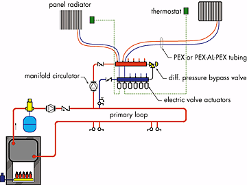
One of the piping concepts that got my attention back when the "new hydronics" concepts from Europe were first emerging in the U.S. market was called a homerun system. Such systems consist of one or more manifold stations that form the beginning and end of a PEX or PEX-AL-PEX circuit to each panel radiator. The concept is shown in Figure 3.The homerun approach offers some attractive features. First, the tubing to each panel radiator seldom needs to be larger than 1/2-inch nominal I.D. In many cases 3/8- or even 1/4-inch nominal I.D. tubing could be used.
The underlying reason is that panel rads can operate with a temperature drop of 30 degrees F to 40 degrees F between their supply and return connections. High temperature drops mean low flow rates. For example, a panel delivering 5,000 Btu/hr. with 170-degree F inlet, and 130-degree F outlet water temperature only needs about 0.25 gpm of flow. This could easily be handled by a 1/4-inch I.D. (10-mm O.D.) tube.
Small diameter PEX or PEX-AL-PEX tubing easily is routed through framing cavities. If you can pull a length of electrical cable from point A to point B, chances are you could also pull through some small diameter PEX or PEX-AL-PEX tubing. This makes the homerun approach ideal for retrofit jobs where framing cavities may have limited access.
There will be some variation in surface temperature when the panel is operated with a high DeltaT. However, this is not of the same concern as it would be with a floor heating circuit. In the latter case, occupants would likely notice the temperature variation as they walk about the room, especially if barefooted. Fortunately, people don't walk around on panel radiators. Here it's the total heat output that counts.
Another advantage is that homerun systems supply the same water temperature to each panel. The size of the panels doesn't have to be adjusted to compensate for supply temperature drops as with series or one-pipe systems. All panels can be sized for the same water temperature and temperature drop. If supply water temperature is reset, all panels benefit equally.
Individual panels can be controlled by either TRVs or electric valve actuators on the manifold. The latter would be wired to individual room thermostats. The end switches of the valve actuators would be wired to operate the pump when any one or more of the thermostats call for heat.
If TRVs are used, be sure to install a differential pressure bypass valve to prevent the circulator from "dead heading" (e.g. operating when none of the TRVs or zone valves is open). Adjust the knob on the differential pressure bypass valve so that it just begins bypassing flow when all the zone circuits are on, then increase the pressure setting just a tad. As the zones close off, the bypass valve will take an increasing percentage of the manifold flow and prevent the circulator from imposing a high-pressure differential on the circuits that remain open. The piping remains quiet and the customer remains happy.
Elegant, Efficient & Comfortable
In my opinion, a selection of panel radiators, each sized and shaped as necessary for the proper heat output and prevailing architectural constraints, and all connected by a homerun distribution system, is the most versatile hydronic retrofit strategy going.It's also an ideal way to handle supplemental heating in high load areas served by radiant floor heating, or to supply a collection of towel warmers in each of several bathrooms, mudrooms, etc. It's one of many hydronic heating strategies that has no rival in the realm of the tin knocker. Deploy it and listen as your customers rave about their elegant, efficient, supremely comfortable and, dare I say, "fashionable" new heating system.


