
Still, even those who recognize the magic of the closely spaced tees in a P/S system often have questions:
Rather than simply state rules-of-thumb answers based on a set of assumptions, I'd rather give you "design tools" that let you evaluate the tradeoffs and find the answers appropriate for each system you design. These tools are based on the same fundamental relationships between flow rate, temperature drop, and heat transfer that we've discussed in previous columns. To make the math easier, I've thrown in a simple spreadsheet that lets you play the "what if" game without need of paper, pencil and calculators.
Seriesous Design
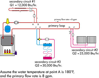
The best known form of P/S piping arranges the secondary loads in sequence along a common primary loop. Such a configuration more specifically is called a series primary loop. An example is shown in Figure 1.Note that each secondary circuit is connected to the primary circuit using a pair of closely spaced tees. These tees should be as close together as possible. Install the tees with the indicated minimum lengths of piping both upstream and downstream. These straight sections of pipe reduce turbulence that can interfere with the tees' ability to "uncouple" the pressure dynamics of one piping circuit from another.
Whenever water flows through a hydronic circuit with series-connected loads a temperature drop occurs across each load. Each operating secondary circuit represents such a load to the series primary loop.
When the secondary circuit's heat output rate and primary circuit's flow rate are known, the temperature drop in the primary loop as it passes an operating secondary circuit can be found using Formula 1:
Formula 1
gTp = k X fp
gTp = temperature drop in the primary loop (degrees F)
Q = rate of heat release by secondary circuit (Btu/hr.)
fp = flow in primary circuit (gpm)
k = 490 for water (use 479 for 30 percent glycol, 450 for 50 percent glycol)
For example: A water-filled primary loop flowing at 10 gpm and supplying 40,000 Btu/hr. to a secondary circuit would see a temperature drop of 8.2 degrees F.
Each temperature drop lowers the water temperature available to the next downstream secondary circuit. It's important to account for this decreasing temperature when deciding how to connect the various secondary circuit to a common primary loop and sizing the heat emitters within each secondary circuit. Figure 2 shows an example of how Formula 1 can be applied in a sequential manner to calculate the water temperature to each secondary circuit.
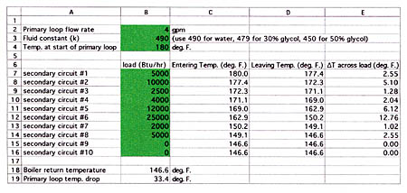
Figures 3a and 3b show a simple spreadsheet that allows these calculations to be performed for up to 10 series-connected secondary circuits. This spreadsheet calculates the fluid temperature just upstream of the first tee at each secondary circuit (entering temperature) and the temperature just downstream of the second tee (leaving temperature).
The user only needs to work with the numbers shown in green.
As printed, it is set up for water (the value of k=490). You can easily change the value of k to simulate antifreeze solutions as noted.
For systems having less than 10 secondary loads, simply enter 0 for the unneeded secondary load cells working backward from secondary load No. 10. For example: Secondary loads Nos. 9 and 10 in the spreadsheet shown are set to 0. This implies 8 secondary loads are present.
Exploiting The Advantages
Series P/S piping is ideal for systems having several secondary loads requiring different supply water temperatures. For example, imagine a system where one secondary circuit provides heat to fin-tube baseboards that often are sized for relatively high water temperatures (180 degrees F is typical).Another secondary circuit serves a group of medium temperature panel radiators, or a staple-up floor heating zone, intended to operate at, say, 150 degrees F. Still, another secondary circuit provides heat to a low-temperature floor heating zone through a variable speed injection mixing system that can work with water temperatures as low as 140 degrees F, even at design conditions.
When such a variety of water temperature requirements exists, the secondary circuits should be connected to the primary loop in order of decreasing water temperature requirement. Those requiring high water temperature should be teed-in near the beginning of the loop, while those able to function at low temperatures should be connected near the end. This arrangement matches the load's temperature requirement with localized water temperature along the primary loop. In some cases, it allows the primary loop to operate with an overall gT as high as 30 degrees F or even 40 degrees F.
The benefits of piping secondary loads in order of decreasing supply temperature requirements can be substantial. The larger the gT of the primary loop, the lower its flow rate can be. This in turn leads to smaller diameter piping and smaller primary circulator. Installation costs as well as operating costs are reduced.
Throughout the system's design life, a properly sized circulator has the potential to save several times its initial cost in reduced electrical consumption.
Want proof? Consider the difference in operating cost between two primary loop circulators, one drawing 200 watts and the other drawing 80 watts. Assuming the primary loop circulator operates 3,000 hours per year at a location where electricity cost 10 cents/kilowatt-hour, the 80-watt circulator saves $36 in electrical cost the first year. Even without inflation figured in that's a $720 savings over a 20-year period. Although few of your customers will ask about the operating cost of small circulators in their system, their apathy shouldn't reduce your efforts to provide the most efficient system possible.
When designing a primary loop for use with a conventional boiler, it's important to verify that the water temperature returning to the boiler when all secondary circuits are operating is high enough to prevent sustained flue gas condensation. A minimum return temperature of 130 degrees F often is suggested. The lower line on the spreadsheet of Figure 3 gives the boiler return temperature for each assumed load scenario.
Picking Primary Pumps
I've often found system designers tend to overcomplicate the task of sizing a circulator for a primary loop. Part of this stems from the notion that the primary circulator somehow helps push flow through the various secondary circuits. This is not true. As far as the primary circulator is concerned, the secondary circuits don't even exist! Those closely spaced tees might as well be couplings.Hence, the primary circulator "sees" the primary loop as a simple series circuit having a given length and pipe size and containing an assortment of piping fittings. Once the pipe size, circuit length and head loss characteristics of these components are defined, the circulator selection process is just like that for any other series piping circuit.
Here's the procedure to follow:
Step 1: Make a list of the secondary circuits you plan to tie into a common primary loop. For each circuit, record the total Btus/hr. required, as well as the assumed supply water temperature needed by that circuit under design conditions.
Step 2: Pick an initial assumed temperature drop for the primary loop under design load condition. (20 degrees F, for example).
Step 3: Calculate an initial estimate for the primary loop flow rate using Formula 2:
Formula 2:
where:
fp = flow rate in primary loop (gpm)
gTp = temperature drop of primary loop at design load (degrees F)
Q = rate of heat input to primary loop (Btu/hr.)
k = 490 for water (use 479 for 30 percent glycol, 450 for 50 percent glycol)
Step 4: Using the flow rate calculated in Step 3, go through the manual calculations demonstrated in Figure 2, or even better, use the spreadsheet of Figure 3 to determine the actual water temperature available at each secondary circuit.
In some cases, the actual supply water temperature available to a given secondary circuit may be quite different from the initial value assumed in Step 1. You now have some options to evaluate. You could resize the heat emitters in that secondary circuit for the actual water temperatures they will see in the proposed design.
Or you could vary the boiler water temperature and the primary loop flow rate, repeat the calculations of Step 3 and see how the temperatures change. You might even try rearranging the order of the secondary circuits along the primary loop and repeating the calculations of Step 3.
Such is the nature of its iterative design. You define a hypothetical arrangement, run the numbers to see how the system would work if built as proposed and then progressively tweak factors that affect its performance until you find an acceptable solution.
Step 5: Once you've settled on the primary flow rate, pick a pipe size to accommodate that flow rate.
Step 6: Estimate the head loss of the primary loop at this flow rate. Include the head loss of the boiler if the primary flow passes through it. If the boiler is connected as a secondary circuit with its own circulator, do not include its head loss in the calculations.
Step 7: Select a circulator that yields the required flow rate at the head requirement determined in Step 5.
That's it, plain and simple.
In a future column, we'll look at some variations of primary/secondary piping. There are several hybrids that better adapt the advantages of the closely spaced tees to the specific needs of the system. In the meantime, don't oversize those primary pumps, and take advantage of deep gTs whenever possible.


