Nothing beats hydronic heating when it comes to zoning versatility. You can zone with circulators, electric zone valves (two-way and three-way), valve actuators on manifolds, or a wide variety of nonelectric thermostatic valves.
Although it's common to use a single method of zone control in basic hydronic systems, nothing says you can't think outside of the basics when the right situation comes along. We recently had just such an opportunity in retrofitting an old church building with hydronic heating. It was an ideal project in which to combine the best of electric and nonelectric zone control.

Mix & Match
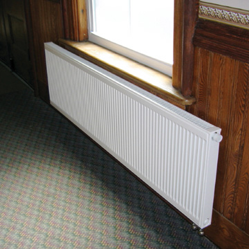
The church consisted of two larger areas - the sanctuary and fellowship room - as well as several smaller areas, such as offices, library, choir room and bathrooms. Given the structure of the building, its occupancy schedule and the budget, we decided to use panel radiators throughout the building. They're durable, relatively easy to install, respond quickly to setbacks and load changes, and can be used with virtually any method of zone control.It made sense to treat the two larger areas of the building (the sanctuary and fellowship room) as two separate zones. Given their size and load requirements, each would require several panel radiators. Although all the panel radiators came with integral flow balancing valves, it didn't make sense to equip each radiator serving these larger areas with individual thermostatic radiator valves (TRVs). Just imagine how different people would constantly readjust such valves at different times. The chances of several TRVs in the same space remaining “in sync” with each other are pretty slim. Besides, who would want to go around to each radiator and adjust the TRVs every time the space needs to go into or come out of a setback period?
Instead, the radiators in each of these larger spaces would be served by a parallel piping arrangement and controlled as a group using a single zone valve operated by a seven-day programmable thermostat. The spaces are warm before people arrive and automatically drop back to unoccupied setting of 60 degrees F at other times.
Homeruns Are Hard To Beat
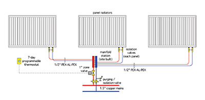
At one point we considered piping these radiator groups using rigid copper tubing in a reverse return arrangement as shown in Figure 1. However, a closer look at the retrofit conditions quickly revealed this approach wasn't going to be easy.The thinking soon moved to flexible tubing. A homerun circuit of 1/2-inch PEX-AL-PEX supplied from a manifold station could serve each panel radiator. This relatively small flexible tubing would be much easier to snake through the various framing cavities, and could be easily attached to wall and ceiling surfaces using plastic standoff clips. Flow to each manifold station could be controlled with a single zone valve. The homerun approach would deliver the same water temperature to each radiator just like rigid reverse return piping. It also keeps the head loss of the distribution system relatively low. A typical piping subassembly for this approach is shown in Figure 2 on the next page.
The other building areas were small in comparison to the sanctuary and fellowship room. A single panel radiator could heat each of these spaces. Here it made sense to use thermostatic radiator valves on each panel to provide room-by-room temperature control. The TRVs provided upper and lower limit stops on the setting range. They could also be equipped with lock rings to prevent big hands as well as little hands from making arbitrary adjustments.

Back In The Mechanical Room
So how do you pull all these piping subassemblies together and coordinate boiler and circulator operation? One of the simplest methods is to give the entire system a “wake-up call” at a specific outdoor temperature. This call enables boiler and circulator operation. With warm water in the boiler and the circulator operating, it's just a matter of which zones are calling for heat at any given time. Let's look at this approach in more detail.When the outdoor temperature drops to 60 degrees F, the system circulator turns on and the boiler is fired, based on outdoor reset control. This can be done using a reset controller with “warm weather shut down” capability and a relay to operate the system pump. It also can be accomplished by combining a basic boiler reset control with a setpoint control that monitors outdoor temperature.
As soon as the system wakes up, boiler temperature climbs to a target value based on the programming of the reset control and the current outdoor temperature. During relatively mild weather, this will typically be the lowest temperature at which the boiler can operate without operating with sustained flue gas condensation. In the church system, which used an oil-fired boiler, the minimum boiler target temperature was set at 130 degrees F. Systems with other types of boilers may require this temperature to be set slightly higher or allow it to be slightly lower. Check with the boiler manufacturer for its recommended minimum operating temperature, and use this as the lower end of the reset range.
Keep in mind that an on/off-type boiler reset control operates with a differential centered on the calculated target temperature. For example, if the calculated target water supply temperature is 130 degrees F, and the differential of the reset control is 12 degrees F, the burner comes on at 124 degrees F and turns off at 136 degrees F. We used an outdoor reset control with an “auto-differential” feature that automatically widens the burner on/off differential as the outdoor temperature increases. This reduces boiler short-cycling under low load conditions.

Head Is A Terrible Thing To Waste
Another important consideration with any system using valves for zoning is limiting the differential pressure across the system circulator under low load (or no load) conditions. Because circulator operation in the church system was based solely on outdoor temperature, it's possible for the circulator to be running when all zone valves and TRVs are closed. This possibility must be addressed to avoid “dead heading” the circulator.There are two ways of dealing with this. The most common - at least for the present - is to install a differential pressure bypass valve (DPBV) and set it to “cap” the maximum differential pressure established between the supply and return mains. In the event that all zones are closed and the circulator is running, some flow will develop through the bypass valve and circulate back through the boiler.
Although this approach limits differential pressure, it does so by dissipating excess head energy imparted to the water by the circulator. Head energy is not free. Your customers indirectly purchase head energy in the form of electricity to operate the circulator. Dissipating excess head energy through a DPBV is like holding slight pressure on your car's brake pedal to limit speed rather than backing off on the gas pedal. You may be able to do this but it's certainly not energy-efficient.
You can think of this concept as “cruise control” for the circulator, much like an outdoor reset control provides “cruise control” for boiler water temperature. Together these techniques increase both the thermal efficiency and distribution efficiency of the system. The day when both techniques will be the norm rather than the exception is quickly approaching.
The church system actually has both types of differential pressure control: a fixed speed circulator with differential pressure bypass valve, and a Wilo Stratos variable speed/constant differential pressure circulator. A toggle switch on the control panel and a pair of ball valves selects which circulator is active.
The variable speed circulator is the default selection. The fixed speed circulator with bypass valve provides a relatively inexpensive back-up. If the church is cold on a Sunday morning due to a circulator problem, it's a lot easier to flip a switch and move a couple valve handles than it is to get out the wrenches.


Happy Thanksgiving!
