

Primary/secondary systems need proper detailing to work correctly.
One of the most important details is preventing heat migration from the primary loop into an inactive secondary circuit.
In 1968 Bell & Gossett produced the “Primary Secondary Pumping Application Manual” (Bullentin No. TEH-775). This publication provided information on how to properly connect secondary circuits to a primary loop so buoyancy driven flow (also called thermosiphoning) would not carry heat into the secondary circuit when its circulator was off, but other secondary circuits attached to the primary loop were operating.
On the supply side of the secondary circuit, B&G showed use of a weighted plug flow check valve to prevent buoyancy driven flow. A weighted plug flow check valve has a forward opening pressure requirement of 0.3 to 0.5 psi. This was sufficient to prevent the slight pressure differential created by hot water on the supply side of the secondary circuit and cooler water on the return side from inducing thermosiphon flow in the circuit. It also compensates for a very small (but not zero) pressure drop across the closely spaced tees that connected the secondary circuit to the primary loop.
Weighted plug flow check valves are still available for several suppliers and can still be used for the above described purpose. However, many modern systems now use spring-loaded check valves to accomplish the same function. The light spring pressure within these valves holds the disk against its seat to prevent forward flow until the pressure differential reaches about 0.5 psi. The spring check valve can be a separate component or a cartridge inserted in the volute of small hydronic circulators. When used as a separate component, there should be at least 12 pipe diameters of straight pipe upstream of the check valve to reduce turbulence entering the valve. If not attenuated, turbulence can cause rattling sounds in some check valves that have metal-to-metal contact between the movable disk and its seat.
A weak thermosiphon flow can develop within the return side piping of a secondary circuit, even when a flow check or spring-loaded check valve is installed on the supply side of the circuit. Hotter water will slowly rise through the center portion of the pipe’s cross section, while water in contact with the pipe walls cools and descends. This effect is not as strong as forward thermosiphon flow, but it can still be annoying and ideally it should be prevented.
The previously cited B&G manual showed two options for preventing thermosiphoning on the return side of a secondary circuit. One was to install another weighted plug flow check valve on the return side of the secondary circuit. The other was to create a “thermal trap” by dropping the return side of the secondary circuit a minimum of 12 in. below the primary loop, and then making a U-turn and connecting to the downstream tee as shown in Figure 1.
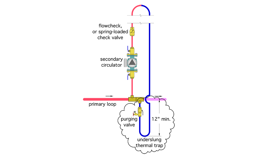
I first read about this in the 1990s. I was intrigued by the concept that hot water would not push downward due to its reduced density. It seemed a thermal trap would be less expensive to create relative to installing another flow check valve. It would be more hydrodynamically efficient (e.g., create less head loss than a flow check valve). Lower head loss is always preferred because it allows a given circulator to achieve a higher flow rate in a circuit — all other detail being the same.
I pondered the following: If a thermal trap could prevent heat migration on the return side of a secondary circuit, why couldn’t it do the same thing on the supply side? Why not use two thermal traps and completely eliminate the need for a cast-iron flow check valve in the circuit?
In addition to cost savings and lower head loss this would reduce iron-to-copper connections in the system, which is better from the standpoint of minimizing galvanic corrosion. It would eliminate having to solder in two MPT x C (male pipe thread to copper) adapter fittings between the copper tubing and FPT body of the flow check valve.
Back in the 1990s, when primary/secondary piping was the darling of the hydronics trade, any incremental improvement in how such systems could be designed or installed would probably be well received. So, inspired by the potential benefits of dual thermal traps I designed a multiload primary/secondary system using them on all secondary circuits.
I was wrong
When that system went into operation, the anticipation of thinking I’d found a new and improved way to stop heat migration quickly turned into disappointing results.
I found the double underslung trapped secondary circuits did not experience migration as long as their secondary circulator remained off after the primary loop first heated up. However, once a secondary circuit became active, and thus hot water was present on the supply side of the circuit, and cooler water was present on its return side, thermosiphoning did occur after the secondary circulator in the circuit was turned off. Furthermore, this thermosiphoning continued until all the secondary circuits served by the primary loop were off and the loop had cooled down substantially from its normal operating temperature.
My disappointment was followed by determination to figure out why this arrangement didn’t work as expected. It turns out the diagnosis was logical and — as the saying goes — hindsight is 20/20.
Take a look at the double underslung thermal traps in Figure 2.
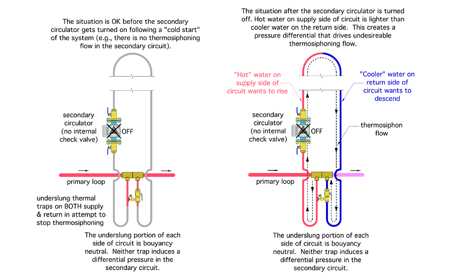
When the secondary circulator is off, each of the thermal traps prevents hot water from moving downward more than a few inches, and thus prevents thermosiphoning in the secondary circuit. The temperature of the water columns on both the supply and return sides of the secondary circuit is essentially the same. There is no pressure differential within the circuit because there is no temperature difference to create it.
That changes when the secondary circuit is turned on. There is now a column of hot water on the supply side of the secondary circuit, and cooler water on the return side. The supply side thermal trap is filled with hot water, and the return side trap filled with cooler water. Thus, each trap is buoyancy neutral. Neither induces thermosiphoning within the secondary circuit.
Unfortunately, this is not the case for the secondary piping above the primary loop. Hot water on the supply side has lower density than cooler water on the return side. The result is a self-perpetuating differential pressure that’s sufficient to carry heat well into the secondary circuit at times when there’s no demand for heat from that circuit. Overheating is the obvious result. This is especially true if one of the secondary circuits operates for domestic water heating during summer when none of the other loads served by the primary loop requires heat.
After the secondary circulator turns off, the return side of the secondary circuit gets even cooler relative to the supply side. This further strengthens the differential pressure and maintains the buoyancy driven flow through the secondary circuit. If any other secondary circuit is operating, a fresh supply of heated water in the primary loop feeds this undesirable process. It continues until all the secondary circuits are off and the supply and return sides of the secondary circuit(s) come back to the same temperature.
The take-away: Don’t use a thermal trap on the supply side of secondary circuits. Use either a weighted plug flow check or a spring-loaded check valve on the supply side. The underslung thermal trap is still fine on the return side — as shown in the 1968 B&G publication.
Hot water will always want to go up, while cooler water will always want to go down. Be sure your future piping inspirations don’t neglect this fact of physics. If you don’t want heat migration, be sure you include proven details to stop it.
This article was originally titled “Double dipping” in the September 2016 print edition of Plumbing & Mechanical.

