
The Glitch
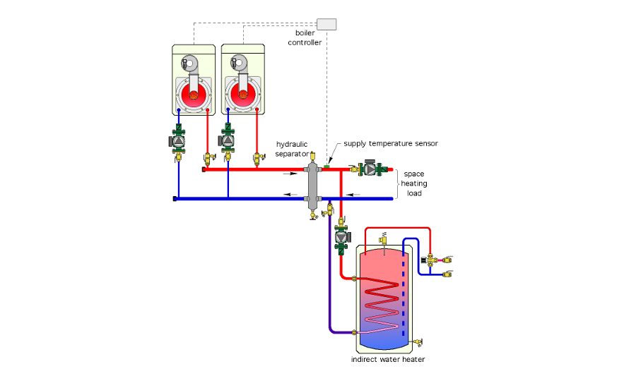
A designer needs to connect an indirect water heater to a multiple boiler system. He selects a hydraulic separator for the project, and connects the piping of the indirect water heater on the same side as the boilers. He also specifies a motorized valve, as shown in the schematic. This valve will close during the domestic water heating cycle so that one or both of the boiler circulators can only drive flow through the indirect water heater.
Study the schematic above and list a few details you think should be changed.
The Fix
One problem with the original design is that the supply temperature sensor for the multiple boiler controller is installed on the outlet side of the hydraulic separator. Most boiler controllers only have a single supply temperature sensor that has to provide feedback to the controller in both the space-heating and domestic-water-heating modes. The sensor cannot provide accurate feedback without flow passing through the piping to which it is attached (as would be the case with the original design).
The cost of a large motorized valve is probably as much if not more than a separate circulator for the indirect water heater. The latter also ensures good flow through the tank’s heat exchanger regardless of flow through the boiler(s). This valve also adds hydraulic resistance in the circuit leading through the left side of the hydraulic separator.
This will erode (but not eliminate) the ability of the hydraulic separator to prevent interaction between the boiler circulators. The latter is important because the reverse return piping shown on the original drawing, while not necessary an error, is usually not necessary, provided the header is sized for a very low pressure drop.
Maintaining flow through the hydraulic separator in both operating modes also allows the air- and dirt-separating functions of the hydraulic separator to remain in effect. Heat loss from the hydraulic separator is reduced during both operating modes by its insulating shell — this shell is an absolute must for any hydraulic separator.
Finally, purging valves, an expansion tank and a makeup water assembly have been added to the subcircuits in the Fix drawing above.
Download a pdf of the February 2016 The Glitch & The Fix.
This was originally published as "Lefty or righty" in Plumbing & Mechanical's February 2016 issue.


