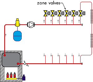

As the zone thermostats reach their setpoint and the associated zone valves close, the distribution system as a whole develops increasing resistance to flow. The overall system flow rate decreases, but the flow rate through each open zone circuit increases. Some of the lanes on the bridge are now blocked off, and it's simply not possible to get the same amount of traffic across, even though traffic moves slightly faster along each lane.
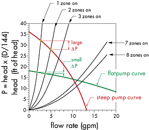
The system curve of the distribution system steepens each time a zone valve closes. Figure 2 shows this effect for a system having several identical floor heating circuits each controlled by its own zone valve.


Where:
DeltaP = pressure differential across pump
H = head added by circulator (in ft. of head)
d = density of fluid being pumped (in lb./cubic ft.) (use 61.3 lb. / cubic ft. for 140-degrees F water)
Anything that changes the flow resistance of the distribution system causes the system curve to either steepen, (for increasing flow resistance), or flatten (for decreasing flow resistance). As the system curve shifts so does the point where it intersects the pump curve.
When a zone valve closes, the system curve steepens forcing the operating point to slide upward along the pump curve. This increases the pressure differential imposed on the zones that remain open. The increased pressure differential increases the flow rate through these zones. At some point the increased flow velocity will probably cause noise in either the zone valve or the piping. And believe me, the sound of a "singing" zone valve is about as soothing as a fourth-grader learning to play the violin.
In some systems the increased differential pressure generated by several inactive zones can partially open what are supposed to be closed zone valves. This causes heat input to zones that are supposed to be off.
Imagine, for example, a system having several zoned space heating circuits and a separate circuit supplying an indirect water heater. Assume all the circuits are controlled by zone valves. The domestic water heater is likely to be the only zone operating during warm weather. It's possible that a high differential pressure across the circulator when the DHW load is operating could lead to hot water "oozing" through the closed zone valves on the space heating circuits. This is especially unappealing when the home's cooling system is running full tilt. I'd say that warm air rising from baseboards when the outside temperature is 90+ degrees F is legitimate cause for a complaint, wouldn't you?
Under Pressure
One way to minimize changes in differential pressure as zone valves open and close is to select a circulator with a relatively "flat" pump curve. Figure 4 shows the curve of such a circulator as well as the curve of a "high head" circulator. Also shown are progressively steeper system curves that represent zone valves closing off in the system.Compare the changes in differential pressure as the operating point shifts upward along the "flat" pump curve to those that would occur along the pump curve of the high head circulator. In both cases the zone circuits that remain on "feel" increased differential pressure as the other zones close, but far less in the system using the circulator with the flat pump curve.
If flatter is better, what do you think an "ideal" pump curve would look like? That's right. It would be a straight horizontal line at some fixed value of differential pressure. A circulator with this pump curve could deliver constant differential pressure regardless of the flow rate passing through it. Unfortunately, no fixed speed centrifugal pump can yield this ideal pump curve. However, several smaller circulators operating in parallel can produce a decent approximation for systems needing relatively high flow rates.
Using a circulator with a flat pump curve in zone valve systems is not a new concept. It's been described in many references over several decades for those willing to learn how to properly select hydronic circulators. Still, I wish I had a dollar for every time someone installed a "high head" pump in a system containing several zone valves, and eventually heard about the problem - literally! In most cases I would bet the installer didn't know if a standard 1/25 horsepower circulator had enough "humph" for a system with more than three or four zones. Immediately following that moment of uncertainty they invoked the ever-popular bigger-is-better selection criteria. Just be glad these guys "design" heating systems rather than airplanes.
Another technique for limiting the differential pressure across the circulator is to install a differential pressure bypass valve as shown in Figure 5. This valve works like a pressure relief valve that "relieves" flow back to the intake side of the circulator rather than to a drain.
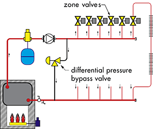
When you adjust a differential pressure bypass valve set the knob so the disc just starts to lift away from its seat when all zone valves are open, then increase the differential pressure setting just a tad. Some valves have a small "window" that let's you see as the valve begins to bypass flow. For those that don't, you can determine the differential pressure across the system when all zones are operating by finding the head at the operating point and converting it to a differential pressure using Formula 1. You could also install pressure gauges on the supply and return sides of the distribution system to determine the pressure differential when all zones are operating.
In my opinion a differential pressure bypass valve should be used in any zone valve system or sub-system that contains more than four zones or uses a circulator having a rating greater than 1/25 horsepower. They should also be used to prevent "dead heading" the circulator in systems where several parallel-piped heat emitters are controlled by thermostatic radiator valves.
The Ultimate Solution
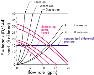
Having just extolled the virtues of differential pressure bypass valves let me now say they represent a "Band-Aid" solution to the ultimate challenge at hand. True, they do prevent the circulator from operating at high differential pressures and, hence, eliminate flow noise and valve seat leakage. However, they do so by throttling away head energy rather than reducing electrical power input to the circulator. It's sort of like limiting the speed of your car by partially applying the brakes instead of backing off on the gas pedal.A more elegant solution to controlling differential pressure as zone valves close is to reduce the speed of the circulator. As the speed decreases, the pump curves shifts to the left and downward on the graph as shown in Figure 6.
As the zone valves open and close and the system curve changes its "steepness," the pump curve of a variable speed circulator can be shifted as necessary to maintain the same differential pressure across the operating zones. The zones that remain on don't sense that other zones have closed. All active zones operate at the same flow rate and differential pressure regardless of which zones are off. Properly controlled, the circulator operates as a constant differential pressure device regardless of the flow passing through it. Just like a circulator with the "ideal" pump curve we discussed earlier.
Variable speed circulators prevent changes in differential pressure and reduce electrical energy use in the process. Such circulators have been used in Europe for several years, and will soon gain market share in North America. At least two major pump manufacturers now have small variable speed circulators on the market. Most vary their speed using a 2-10 volt DC or 4-20 milliamp control signal.
What remains is for manufacturers to develop a simple, low-cost differential pressure sensor that can serve as the eyes for the circulator, telling it when and by how much to vary its speed.
Another possibility is to vary to circulator's speed based on the temperature differential across the distribution system. In this scenario, the controller operating the circulator is set to maintain a fixed temperature drop across the distribution system. When a zone valve closes less heat is released by the distribution system and, hence, the temperature drop from the supply to return header drops. The temperature sensors associated with the pump controller sense this change as it develops and reduces the speed of the pump downward to maintain a set temperature drop.
Look for one or more of these strategies to show up in the not too distant future on a hydronic system near you. In the meantime, use a circulator with a flat pump curve and differential pressure bypass valve on those zone valve systems to keep both your piping and your complaint line quiet.


