Hydronics Workshop: Small, Simple, Sustainable
Are we
ready for what’s coming?
The depths of winter, and start of a new decade, provide a good time to review photos, magazines and other such materials that have been accumulating in your office for months, possibly even years. Perhaps it’s photos of installations you or others did 15 years ago, old literature promoting the virtues of radiant floor heating or newsletters that show state-of-the-art hydronic systems from the ’90s.
Besides cleaning the office, you’ll get to revisit the “thinking” involved with system design and installation from the not-too-distant past. Thinking that was certainly different from that used in the ’70s and ’80s, and thinking that inevitably will be different from that in the future.
I, like many others, was fortunate to work on such projects, which spread ample income to many construction professionals. Projects where a wall full of controllers, circulators, and line after line of perfectly level, plumb and shinny copper tubing earned kudos from manufacturers, peers and trade associations. Times were good and checks didn’t bounce.
Despite the gloom of daily news cycles, I feel optimistic that the North American hydronics industry can flourish in the future, if it recognizes and adapts to building trends based on more pragmatic choices in design, budget and environmental impact.
Future homes will be smaller and more energy efficient than those built from 1980 through the last decade. This trend is already on the radar. U.S. Census data shows that for the first time in more than a decade, the average size of new homes dropped 11 percent during 2008. Interest in energy conservation is further driven by the average consumer’s zeal to be “green.” Even our president recently told us “insulation is sexy”!
So are we - the North American hydronics industry - ready to capitalize on this trend?
One way to gauge this is by examining our current repertoire of “hydronic solutions.”
For example, what is your “hydronic solution” when presented with plans for a new home built using structural insulated panels or insulated concrete forms, and having a design heat loss of 18,000 Btu/hr.? No, I didn’t drop a zero there - I really meant 18,000 not 180,000 Btu/hr.
Some of you may envision the solution as the smallest wall-hung mod/con boiler you can find, tied to three or four zoned manifolds supplying floor heating circuits. You realize that floor heating uses low water temperatures that can make that mod/con boiler condense itself into 98+ percent efficiency. Perhaps you envision your green-minded homeowner reacting to the 98+ percent thermal efficiency with an impulsive, “When can you begin the installation?”
Let’s say the house with the 18,000 Btu/hr. heat loss has 1,800 square feet of living space and we just fill up that space with floor heating. At design load, the upward heat flux from the floor is only 10 Btu/hr./ft2. If the room temperature is 70 degrees F, the average floor temperature will be about 75 degrees F. That’s a few degrees cooler than our normal skin temperature.
So guess what happens when a bare hand or foot is placed on a 75 degree F floor? You got it - heat moves from flesh to floor. Most people expect floor heating to work the other way around and they’re going to be disappointed when they discover otherwise.
Now, you might say this situation is no worse than a forced-air system holding the room air temperature at 70 degrees F. In fact, it’s even better because the floor is a few degrees above where it would be with a forced-air system. Agreed. The problem is that the owner has spent considerably more money to install hydronic floor heating and, in most cases, will be expecting substantially better comfort. They remember the toasty toes pictures shown in floor heating literature.
Before you fall back to “but it’s 98+ percent efficient,” think about what the furnace industry currently offers. There are many makes and models of condensing furnaces that all suck in nominal 65 degree F return air and, thus, operate at efficiencies every bit as good, if not slightly higher, than your almost 300-percent-oversized wall-hung mod/con boiler. You and I aren’t going to “beat” the furnace industry at the thermal efficiency game.
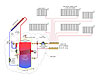
The system shown in the figure above is a start toward these requirements.
The heart of this system is a super-insulated storage tank/heat source. It would have a minimum of 3-inch urethane insulation all around and special detailing at connections to all but eliminate heat migration.
A simple, condensing-capable combustion system, with a nominal 3:1 turndown ratio, provides heat to the upper portion of the carbon steel tank. Stratification keeps that heat at the top, allowing the bottom to supply a drainback solar subsystem at the lowest possible collector inlet temperatures.
The thermal mass of the tank’s water, rather than a potentially finicky ultra-high turndown combustion system, provides the buffering necessary to serve a highly zoned distribution system.
Domestic water is heated “on demand” by a small stainless-steel heat exchanger mounted externally to the tank; thus, it is easily serviceable or replaceable if necessary. The moment there’s a demand for hot water, a flow switch activates a very small circulator that moves heated water from the tank through the hot side of this heat exchanger. The scant thermal mass of a brazed plate heat exchanger allows it to supply heated water within a couple of seconds. The thermostatic mixing valve at its outlet protects against potentially high-temperature DHW during sunny periods when the tank is likely to be quite hot. The minimal domestic water content in the system provides a hedge against legionella.
Panel radiators supplied from a homerun distribution system deliver space heating. The panels are sized to operate on 120-135 degree F water at design load. Keep in mind that the room heat loads supplied by these panels may be in the range of 2,000-3,000 Btu/hr. at design load. A 24-inch-by-48-inch-by-4-inch panel radiator with an average water temperature of 125 degrees F can provide 3,000 Btu/hr. output. The panel sizes remain reasonable, even at reduced supply water temperature.
Return temperatures to the heat source would be 25 to 30 degrees lower than supply temperature under design load. The combustion system could operate in condensing mode most of the time.
The output from each radiator is regulated by a nonelectric thermostatic valve. Each room operates as a separate zone and can respond to internal heat gains from sunlight, occupants or equipment. Such gains can alter expected heating loads to a greater degree in well-insulated homes. The ability to respond to them - and respond quickly - is crucial to maintaining comfort.
The ECM-based, variable-speed circulator automatically adjusts speed and wattage based on the current flow demands of the system. At design load, this circulator could likely handle the entire house on about 30 watts of electrical input. Under partial load conditions, the electrical input wattage could be in the single digits. That’s “real” green - from an environmental and economic standpoint.
A three-way mixing valve protects the distribution system from potentially high-temperature water during sunny periods. It also provides reset control of supply water temperature.
The captive air volume at the top of the storage tank serves as the system’s expansion volume as well as the drainback reservoir for the solar subsystem. No external expansion tank or drainback tank is needed.
Solar input is straight from the collector to the tank - no heat exchanger, no antifreeze, no air separator, no purging valves, no heat dump. From the solar thermal standpoint, it’s about as simple as it gets.
The “cloud” around the core of the drawing includes all the hardware that would be consolidated into a pre-engineered, preassembled appliance. Doing so keeps field installation time to a minimum, eliminates issues such as circulator sizing and gets the system online quickly.
I’m sure there are other ways to approach the coming market for low- energy-use “green” homes. I’m also sure that other “camps” within the HVAC industry are making plans to compete in this emerging market sector. Are we?
The depths of winter, and start of a new decade, provide a good time to review photos, magazines and other such materials that have been accumulating in your office for months, possibly even years. Perhaps it’s photos of installations you or others did 15 years ago, old literature promoting the virtues of radiant floor heating or newsletters that show state-of-the-art hydronic systems from the ’90s.
Besides cleaning the office, you’ll get to revisit the “thinking” involved with system design and installation from the not-too-distant past. Thinking that was certainly different from that used in the ’70s and ’80s, and thinking that inevitably will be different from that in the future.
What's Changed?
The hydronic heating market enjoyed sustained double-digit growth during much of the last two decades. Before the economic brakes got slammed on, many of our clients had construction projects that screamed “BIG, COMPLEX and EXPENSIVE.”I, like many others, was fortunate to work on such projects, which spread ample income to many construction professionals. Projects where a wall full of controllers, circulators, and line after line of perfectly level, plumb and shinny copper tubing earned kudos from manufacturers, peers and trade associations. Times were good and checks didn’t bounce.
Despite the gloom of daily news cycles, I feel optimistic that the North American hydronics industry can flourish in the future, if it recognizes and adapts to building trends based on more pragmatic choices in design, budget and environmental impact.
Future homes will be smaller and more energy efficient than those built from 1980 through the last decade. This trend is already on the radar. U.S. Census data shows that for the first time in more than a decade, the average size of new homes dropped 11 percent during 2008. Interest in energy conservation is further driven by the average consumer’s zeal to be “green.” Even our president recently told us “insulation is sexy”!
So are we - the North American hydronics industry - ready to capitalize on this trend?
One way to gauge this is by examining our current repertoire of “hydronic solutions.”
For example, what is your “hydronic solution” when presented with plans for a new home built using structural insulated panels or insulated concrete forms, and having a design heat loss of 18,000 Btu/hr.? No, I didn’t drop a zero there - I really meant 18,000 not 180,000 Btu/hr.
Some of you may envision the solution as the smallest wall-hung mod/con boiler you can find, tied to three or four zoned manifolds supplying floor heating circuits. You realize that floor heating uses low water temperatures that can make that mod/con boiler condense itself into 98+ percent efficiency. Perhaps you envision your green-minded homeowner reacting to the 98+ percent thermal efficiency with an impulsive, “When can you begin the installation?”
System Prototype
Beyond Thermal Efficiency
Now don’t get me wrong - high thermal efficiency is good. It’s an irrefutable part of being green. But it’s not the total picture. If the hydronics industry fails to provide comfort, convenience and reliability, we’re going to lose market share to a spectrum of competing options. Can you say mini-split, through-the-wall gas-fired cabinet heaters or even electric heat?Let’s say the house with the 18,000 Btu/hr. heat loss has 1,800 square feet of living space and we just fill up that space with floor heating. At design load, the upward heat flux from the floor is only 10 Btu/hr./ft2. If the room temperature is 70 degrees F, the average floor temperature will be about 75 degrees F. That’s a few degrees cooler than our normal skin temperature.
So guess what happens when a bare hand or foot is placed on a 75 degree F floor? You got it - heat moves from flesh to floor. Most people expect floor heating to work the other way around and they’re going to be disappointed when they discover otherwise.
Now, you might say this situation is no worse than a forced-air system holding the room air temperature at 70 degrees F. In fact, it’s even better because the floor is a few degrees above where it would be with a forced-air system. Agreed. The problem is that the owner has spent considerably more money to install hydronic floor heating and, in most cases, will be expecting substantially better comfort. They remember the toasty toes pictures shown in floor heating literature.
Before you fall back to “but it’s 98+ percent efficient,” think about what the furnace industry currently offers. There are many makes and models of condensing furnaces that all suck in nominal 65 degree F return air and, thus, operate at efficiencies every bit as good, if not slightly higher, than your almost 300-percent-oversized wall-hung mod/con boiler. You and I aren’t going to “beat” the furnace industry at the thermal efficiency game.
A New Paradigm
I believe the opportunity lies in development of a hydronic appliance and associated delivery system that’s specifically tailored to low-load homes. It must allow for zoning - which has been, is and will remain a premier benefit of hydronics. It must handle very small loads without short-cycling the burner. It must have very low standby heat loss. Having the ability to interface with some type of renewable energy input would certainly be good, especially from a marketing perspective. Perhaps most important, the new approach must be simple, reliable and quickly deployable without custom engineering.The system shown in the figure above is a start toward these requirements.
The heart of this system is a super-insulated storage tank/heat source. It would have a minimum of 3-inch urethane insulation all around and special detailing at connections to all but eliminate heat migration.
A simple, condensing-capable combustion system, with a nominal 3:1 turndown ratio, provides heat to the upper portion of the carbon steel tank. Stratification keeps that heat at the top, allowing the bottom to supply a drainback solar subsystem at the lowest possible collector inlet temperatures.
The thermal mass of the tank’s water, rather than a potentially finicky ultra-high turndown combustion system, provides the buffering necessary to serve a highly zoned distribution system.
Domestic water is heated “on demand” by a small stainless-steel heat exchanger mounted externally to the tank; thus, it is easily serviceable or replaceable if necessary. The moment there’s a demand for hot water, a flow switch activates a very small circulator that moves heated water from the tank through the hot side of this heat exchanger. The scant thermal mass of a brazed plate heat exchanger allows it to supply heated water within a couple of seconds. The thermostatic mixing valve at its outlet protects against potentially high-temperature DHW during sunny periods when the tank is likely to be quite hot. The minimal domestic water content in the system provides a hedge against legionella.
Panel radiators supplied from a homerun distribution system deliver space heating. The panels are sized to operate on 120-135 degree F water at design load. Keep in mind that the room heat loads supplied by these panels may be in the range of 2,000-3,000 Btu/hr. at design load. A 24-inch-by-48-inch-by-4-inch panel radiator with an average water temperature of 125 degrees F can provide 3,000 Btu/hr. output. The panel sizes remain reasonable, even at reduced supply water temperature.
Return temperatures to the heat source would be 25 to 30 degrees lower than supply temperature under design load. The combustion system could operate in condensing mode most of the time.
The output from each radiator is regulated by a nonelectric thermostatic valve. Each room operates as a separate zone and can respond to internal heat gains from sunlight, occupants or equipment. Such gains can alter expected heating loads to a greater degree in well-insulated homes. The ability to respond to them - and respond quickly - is crucial to maintaining comfort.
The ECM-based, variable-speed circulator automatically adjusts speed and wattage based on the current flow demands of the system. At design load, this circulator could likely handle the entire house on about 30 watts of electrical input. Under partial load conditions, the electrical input wattage could be in the single digits. That’s “real” green - from an environmental and economic standpoint.
A three-way mixing valve protects the distribution system from potentially high-temperature water during sunny periods. It also provides reset control of supply water temperature.
The captive air volume at the top of the storage tank serves as the system’s expansion volume as well as the drainback reservoir for the solar subsystem. No external expansion tank or drainback tank is needed.
Solar input is straight from the collector to the tank - no heat exchanger, no antifreeze, no air separator, no purging valves, no heat dump. From the solar thermal standpoint, it’s about as simple as it gets.
The “cloud” around the core of the drawing includes all the hardware that would be consolidated into a pre-engineered, preassembled appliance. Doing so keeps field installation time to a minimum, eliminates issues such as circulator sizing and gets the system online quickly.
I’m sure there are other ways to approach the coming market for low- energy-use “green” homes. I’m also sure that other “camps” within the HVAC industry are making plans to compete in this emerging market sector. Are we?
Links
Looking for a reprint of this article?
From high-res PDFs to custom plaques, order your copy today!


